DMC 3050 Manuale utente

OWNER’S MANUAL
GRAVITY FLOW
GRAIN SPREADERS
MODELS
3050 AND 10,000
PNEG-1150
PNEG-1150
Date: 9-21-06


Thismanualcontainsinformationthatisimportantforyou,theowner/operator,toknowand
understand.Thisinformationrelatesto protectingpersonal safety andpreventing
equipment problems.Itistheresponsibilityoftheowner/operator to inform anyone
operatingorworkingin the area ofthisequipmentof these safety guidlines.Tohelpyou
recognizethisinformation,weuse the symbols that are definedbelow.
Pleasereadthe manual and pay attentiontothese sections. Failure toreadthis manual
andit’ssafety instructions is amisuseof the equipment andmaylead to serious injuryordeath.
SAFETY GUIDELINES
DANGER indicatesanimminentlyhazardoussituationwhich,ifnot
avoided,willresultindeathor serious injury.
This is the safety alert symbol. It is used to alert you to potential
personal injury hazards. Obey all safety messages that follow
this symbol to avoid possible injury or death.
WARNING indicates a potentially hazardous situation which, if not
avoided,couldresultindeathorseriousinjury.
CAUTION indicatesa potentially hazardous situation which, ifnot
avoided,mayresultinminorormoderateinjury.
CAUTION used without the safety alert symbol indicates a potentially
hazardoussituationwhich,ifnotavoided,may result in property
damage.
NOTE indicatesinformationabouttheequipmentthatyoushould
pay special attention to.

1. Besureelectricalpower is disconnectedprior to enteringthe bin.
2. DoNOTenterabinwhile the unit isoperatingwithout proper eye protection.
3. DoNOTattempttoservice or adjust theunit from a ladderunless the ladder is
securedto another piece ofequipment or tothe bin. The grainspreader can
swingandwill not support a ladder.
4. ReadandunderstandtheOperator’sManual.
WARNING
Failure to follow these instructions may result in
personal injury or property damage.
3050 3050 With Chute
Extension and
Counterweight 10,000
Dry Grain 15' - 36' Diameter 15' - 42' Diameter 36' - 72' Diameter
3000 BPH 5000 BPH 10,000 BPH
SPREADING CAPACITIES
NOT recommended for grain wetter than 16% moisture content.

5
AssemblyGravity Flow Spreader

6
Assembly Gravity Flow Spreader
ASSEMBLY of 3050 SPREADERS
1. Assemble 3071027 Chute to 3071034 Hopper with (6) 3/8” x 1” bolts, lockwashers and
nuts.
2. Assemble 3071026 Chute to the end of the first chute with (3) 3/8” x 1” bolts,
lockwashers and nuts depending on the size of the bin.
a. 21’ diameter & smaller - assemble in the shortest position - see below.
b. Over 21’ thru 30’ diameter - assemble in the middle position - see below.
c. Over 30” thru 36’diameter - assemble in the longest position - see below.
d. The 3050 spreader can be used for bin diameters up to 42’ diameter when a chute
extension option (3079009) is installed between the first & second chutes. The
counter weight option (3079011) must be installed when using the chute exten-
sion - see below.
3. Attach the 3071029 Curved Slinger to the bottom at the end of the second chute and to
the straightening vane of the first chute (or 3071028 Straight Extension) with (2) 3/8” x 1”
bolts, lockwashers and nuts.
4. When the second chute is in the middle or longest position, the 3071028 Straight Exten-
sion is assembled to the bottom of the chute with (2) 3/8” x 1” bolts, lockwashers and
nuts. This extension is not used when the chute is assembled in the shortest position.
5. For Model 3050 with Counterweight Options: Assemble the 3071040 Counter Weight
Tube to the back of the hopper with (2) 3/8” x 1” bolts, lockwashers and nuts.
Up to 21’ Diameter Bin
30’ to 36’ Diameter Bin
21’ to 30’ Diameter Bin
36’ to 42’ Diameter Bin

7
AssemblyGravity Flow Spreader
ASSEMBLY of 3050 SPREADERS (continued)
6. Assemble the 3071037 Center Spider to the hopper by first placing a 1” flat washer on
the center shaft and inserting the shaft through the bearings in the center of the hopper.
Place another 1” washer on the bottom of the shaft and secure with the 3FH1224 over-
center retaining pin. Pull the center spider back up until the bottom washer is up against
the bottom bearing and tighten the setscrews in both the top and bottom bearings.
7. Assemble the (3) 3071039 Telescoping arms to the arms of the center spider, lock in
place by inserting a 3/8” x 1” bolt into the weldnut and tightening to the spider arm. The
standard arms are 12” long. Telescoping arms 18” long are available in option 3079010
for larger diameter fill rings (36” to 50”) and will fit the fill openings from 26” to 40” in
diameter.
AT THE FILL RING OF THE BIN
8. Drill (3) 13/32” diameter holes equally spaced around the fill ring. Attach the 3071038
Angle Brackets to the fill ring with 3/8” x 1” bolts, flat washers, lockwashers and nuts.
Thread a 3/8” nut and a flat washer onto the stud of each of the angle brackets.
9. Attach a lifting cable or rope to the center spider and lift the assembled spreader up to
the fill ring of the bin. Loosen each of the telescoping arms and attach them to the studs
on the angle brackets; secure with flat washers and 3/8” nuts.
10. For Model 3050 with Counterweight Options: When the spreader has been lifted so it
clears the floor, slide the 3071042 Counterweight onto the tube and adjust it until the
spreader hangs with the chute slightly elevated. Secure in place by tightening the
setscrew.
11. Center the spider assembly in the fill ring and lock in place by tightening the 3/8” x 1”
bolt in each of the telescoping arms.
12. Level the spreader by turning the nut under the end of each of the telescoping arms.
The spreader is level when it does not coast to a low spot. Lock the spreader in position
by tightening the 3/8” nuts on top of the ends of the telescoping arms.
NOTE: THE SPREADER WILL NOT FUNCTION PROPERLY IF IT IS NOT LEVEL.

8
Assembly Gravity Flow Spreader
ASSEMBLY OF THE 10,000 SPREADER
(Refer to the exploded views in the parts section)
1. Assemble the 3072024 Center Shaft & Chute to the bottom of 3072020 Main Chute with
(6) 3/8” x 1” bolts, lockwashers and nuts.
2. Attach the 3072013 Counter Weight Support Tube to the back of the main chute with (2)
3/8” x 1” bolts, lockwashers and nuts.
3. Slide the 3072009 Counter Weight Support Channel over the shaft extending out of the
center chute and fasten to the bottom of the main chute with (2) 5/16” x 1” carriage bolts,
flat washers, lockwashers and nuts. Attach the other end of the channel to the counter
weight tube with a 3/8” x 3 1/2” bolt, lockwasher and nut.
4. Assemble (2) PT0140 1 1/4” Bearings with cast housings to the top of the channels in
the spreader hopper with (4) 7/16” x 1 1/2” bolts, lockwashers and nuts. Do not tighten
the mounting bolts at this time.
5. Slide the hopper and bearings over the center-chute shaft. Make sure to place the
bearing-locking collar, rubber washer and steel washer on top of each bearing. Insert
the 3FH1224 Snap Over Retaining Pin through the hole in the top of the shaft.
6. Tighten the mounting hardware for the two bearings and lift the hopper up on the shaft
as far as possible. Lock the bearings in place by tightening the locking collars in a
counter-clockwise direction when viewed from the top of the hopper.
7. Thread a 1/2” nut and flat washer onto each of the three studs on the top of the hopper.
Attach a 3072014 Angle Hanger to each stud and secure with a flat washer and 1/2” nut.
8. Build a frame into the top and center of the bin to support the spreader. The outside face
of the 3 angle hangers on the hopper form a 21” diameter circle so the frame should be
constructed in a triangle to allow the angle hangers to be bolted directly to the frame
with (3) 3/8” x 1” bolts, flat washers, lockwashers and nuts. (See Figure 1 on next page.)
9. Attach a lifting cable to the center of the hopper and lift the spreader until it clears the
floor. Slide the counter weight onto the tube and adjust its position until it hangs with the
chute slightly elevated. Secure in place by tightening the setscrew on the weight. Fin-
ish lifting the spreader to the frame constructed in step #8 and bolt into place.
10. Level the spreader by adjusting the bottom 1/2” nuts on each of the studs on the hopper.
The spreader is level when it does not coast to a low spot. Lock in position by tighten-
ing the top nuts.
NOTE: THESPREADER WILLNOT FUNCTION PROPERLYIF IT IS NOT LEVEL.

9
OperationGravity Flow Spreader
OPERATION OF SPREADERS
Gravityflow spreaders rotate and spreadgrain because of the forceof the falling grain against
the curved vanes in the spreader chute. The minimum flow rate depends on the density and
moisture content as well as the velocity of the grain entering the spreader. Grain above 16%
moisture and lightweight grains at a low flow rate generally will not generate enough force to
rotate the spreader chute properly.
Uneven distribution of grain to one side of the bin can be caused by the following condi-
tions:
a. Grain is not entering the spreader at the center of the hopper. Readjust the down
spout to direct the grain vertically to the center of the hopper.
b. The spreader is not level. Adjust the hanging brackets until the spreader is level.
Check by swinging the chute by hand several times. It should coast to a stop and be
pointing in a different direction each time.
c. The bearings may be seizing. Check it by swinging the chute by hand.
d. The flow of grain may not be enough to swing the chute uniformly. Observe the
spreader in operation to see if the grain moves the chute.
Figure 1 - Model 10,000 Installation
11
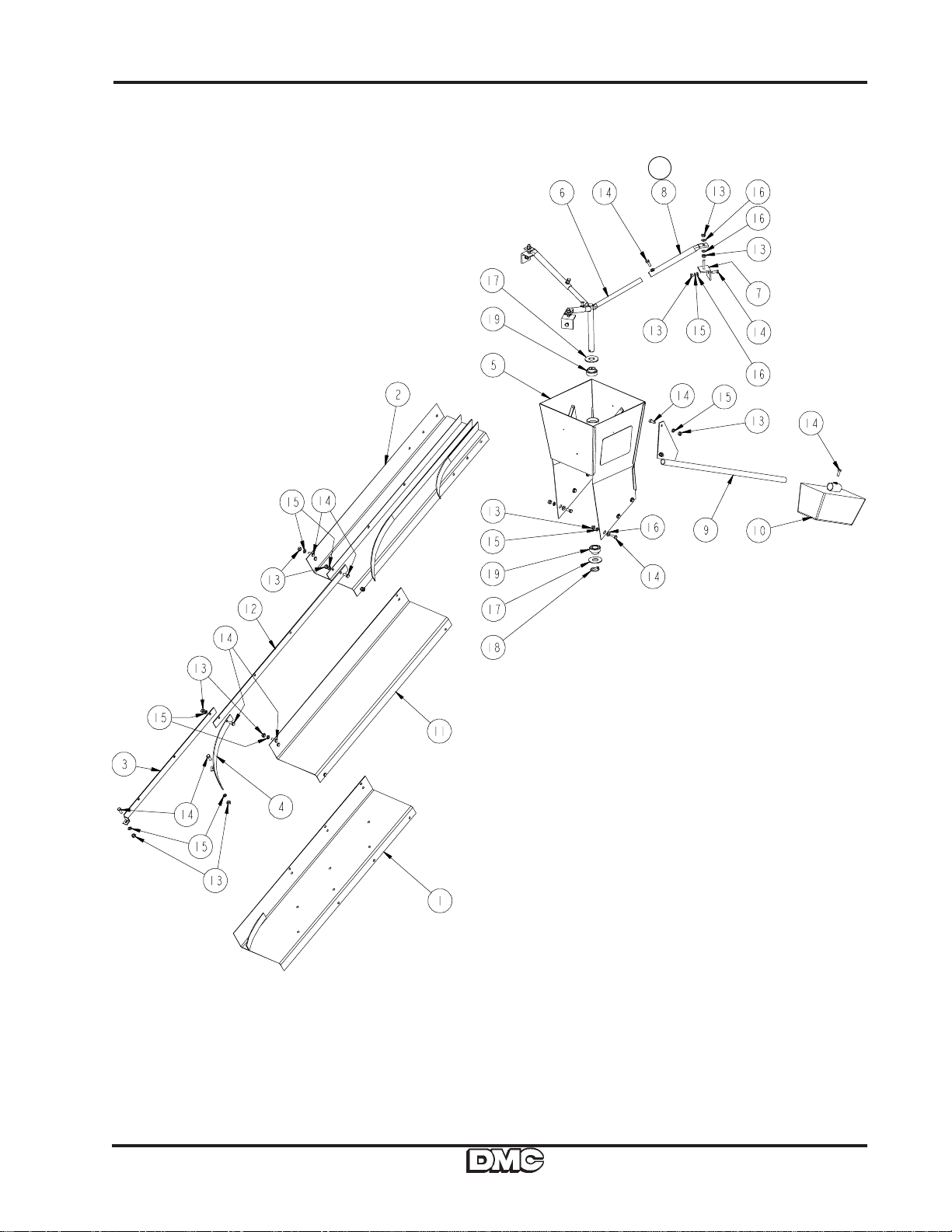
Parts ListGravity Flow Spreader
Model 3050 Parts
Option8a
OptionOption
Option
Questo manuale è adatto per i seguenti modelli
1
Indice
Altri manuali DMC Spargitore


Manuali Spargitore popolari di altre marche


Fisher
Fisher POLY-CASTER 78601 Manuale utente

TurfEx
TurfEx RS7200 Manuale del proprietario

Ferris
Ferris Pathfinder Series Manuale utente

Fayat Group
Fayat Group DYNAPAC S100 Guida alla risoluzione dei problemi

Art's-Way Manufacturing
Art's-Way Manufacturing X700 Manuale di installazione e funzionamento

EASTMAN
EASTMAN CR 500 Manuale utente


