DoAll ZV-3620 Manuale utente

ZV-3620
Serial No: 565-03101 to
Band Sawing Machine
Instruction Manual

DAMAGE CLAIM PROCEDURES
VISIBLE DAMAGE AT THE TIME OF DELIVERY:
1. Note damage on carrier’s delivery receipt. Accept the shipment. It can be returned later if repairs
are not possible in the eld.
2. Request a “damage inspection” from the delivery carrier:
a. The carrier will send his own people or contract an independent agency to make the
inspection.
b. The inspector will request a signature on the report and leave a copy.
c. The carrier “damage inspection” report is not nal. If additional damage is found when
repairs are started, contact the carrier for another inspection; or at least give them the
details of the damage.
3. Do not move the equipment from the receiving area and keep all shipping materials until carrier
“damage inspection” report is complete.
4. If possible, take photographs of the damage and keep them for your les. Photos could possibly
prove a claim at a later time.
5. Keep a record of all expenses and be sure they are documented.
6. Repair damage in the eld whenever possible. Carriers encourage this to keep expenses down.
7. You have nine (9) months to le a claim.
1. You have fourteen (14) days to report damage not noted at time of delivery.
a. Report damage as soon as possible. This makes it easier to prove that it did not happen
at cosignee’s plant.
b. Inspect machine(s) carefully before moving from the receiving area. Again, if machine is
not moved, it is easier to prove your case.
2. Request a “damage inspection” from the delivery carrier:
a. The carrier will send his own people or contract an independent agency to make the
inspection.
b. The inspector will request a signature on the report and leave a copy.
c. The carrier “damage inspection” report is not nal. If additional damage is found when
repairs are started, contact the carrier for another inspection; or at least give them the
details of the damage.
3. Do not move the equipment from the receiving area and keep all shipping materials until carrier
“damage inspection” report is complete.
4. If possible, take photographs of the damage and keep them for your les. Photos could possibly
prove a claim at a later time.
5. Keep a record of all expenses and be sure they are documented.
6. Repair damage in the eld whenever possible. Carriers encourage this to keep expenses down.
7. You have nine (9) months to le a claim.
CONCEALED DAMAGE:

i
MODEL FIRST SERIAL NO. LAST SERIAL NO.
ZV-3620 565-03101
PRINTED IN U.S.A.
OPERATOR'S INSTRUCTION MANUAL
METAL CUTTING BAND SAW
DoALL SAWING PRODUCTS
2375B TOUHY AVENUE
ELK GROVE, ILLINOIS 60007 U.S.A.
PB-507.5 (2-10)
The following registered trademarks of the DoALL Company are used in this manual:
DoALL, Dart, Tensigage and Zephyr.
PLEASE READ THIS MANUAL CAREFULLY BEFORE OPERATING THE MACHINE!
For Sales, Parts and Service, call 1-888-362-5572
For your information and future reference, pertinent data concerning your machine
should be written in the spaces provided above. This information is stamped on
a plate attached to your machine. Be sure to provide machine model and serial
numbers with any correspondence or parts orders.
Specications contained herein were in effect at the time this manual was approved
for printing. The DoALL Company, whose policy is one of continuous improvement,
reserves the right, however, to change specications or design at any time without
notice and without incurring obligations.

ii
TABLE OF CONTENTS
How to read your serial number:
MACHINE DIMENSIONS
Floor Plan ............................................................... 1
Floor Plan With HMD Hydraulic Table .................... 2
Front View .............................................................. 3
Front View With HMD Hydraulic Table ................... 4
MACHINE FEATURES
Front View .............................................................. 5
Front View With HMD Hydraulic Table ................... 6
Rear View ............................................................... 7
Raer View With HMD Hydraulic Table .................... 8
INSTALLATION
Location .................................................................. 9
OSHA Notice!! ........................................................ 9
Unpacking ............................................................... 9
Cleaning ................................................................. 9
Lifting ...................................................................... 9
Machine Installation and Alignment ........................ 9
Electrical Installation ............................................... 10
Table Alignment (Standard) .................................... 10
Table Alignment (HMD Table) ................................. 11-12
Preparation for Use ................................................ 12
OPERATION
Safety Precautions ................................................. 13
Friction Sawing ....................................................... 13
Machine Controls .................................................... 13-14
Table Controls ......................................................... 14
Band Speed Control ............................................... 15
Saw Band Tension Handwheel ............................... 15
Saw Band Tracking Lever ....................................... 15
Saw Band Preparation ............................................ 15-17
Post Adjustment ...................................................... 17
Spark Guard ........................................................... 17
Worktable and Adjustments .................................... 17-18
Dust Spout .............................................................. 18
Hydraulic Brake ...................................................... 18
Typical Sawing Procedures .................................... 18-19
LUBRICATION
Lubrication Chart .................................................... 20
Lubrication Diagram ............................................... 21
MAINTENANCE
Changing Belt ......................................................... 22
Electric Motors ........................................................ 22
Head Components .................................................. 22
Hydraulic Brake ...................................................... 22
Hydraulic System .................................................... 22-23
Hydraulic Table (Optional) ...................................... 23
Saw Guides ............................................................ 23
Machine Cleaning ................................................... 23
Bandwheel Tire Replacement (Sheet Metal
Bandwheels) ........................................................ 24-25
Bandwheel Tire Replacement (Cast Aluminum
Bandwheels) ........................................................ 25-26
TROUBLE SHOOTING .................................. 27-29
ACCESSORIES
Disc Cutter .............................................................. 30
Rip Fence ............................................................... 30
Worklamp ............................................................... 30
Magnier ................................................................. 30
Chip Blower ............................................................ 30
DBW-15 Buttwelder ................................................ 31
Workholding Jaw .................................................... 31
Secondary Table ..................................................... 31
Hydraulic Tables ..................................................... 31-32
Glide Table .............................................................. 32
Optional Saw Guides .............................................. 32
Extra Work Height .................................................. 32
Hydraulic Band Tension .......................................... 32
Band Lubricator ...................................................... 32
Dust Collector ......................................................... 32
Safety Equipment ................................................... 33
Material Handling Equipment ................................. 33

1
MACHINE DIMENSIONS
INCHES (± .03)
MILLIMETERS (± 1 mm)
FLOOR PLAN
Table Dimensions
Standard
Table
Glide
Table
Hydraulic
Table
A36.25
(920.8)
32.63
(828.8)
41.00
(1041.4)
B30.50
(774.7)
25.39
(644.9)
32.00
(812.8)
Optional

2
MACHINE DIMENSIONS (Continued....)
INCHES (± .03)
MILLIMETERS (± 1 mm)
FLOOR PLAN With HMD HYDRAULIC TABLE

3
MACHINE DIMENSIONS (Continued....)
INCHES (± .03)
MILLIMETERS (± 1 mm)
FRONT VIEW
Dimensions
A B C
Work
Height
20.00" (508.0) 15.50" (393.7) 103.25" (2622.6)
30.00" (762.0) 25.50" (647.7) 113.25" (2876.6)
36.00" (914.4) 31.50" (800.1) 119.25" (3029.0)
42.00" (1066.8) 37.50" (952.5) 125.25" (3181.4)

4
MACHINE DIMENSIONS (Continued....)
INCHES (± .03)
MILLIMETERS (± 1 mm)
*"A" and "B" Is Dependent On Work Height Ordered.
FRONT VIEW With HMD HYDRAULIC TABLE

5
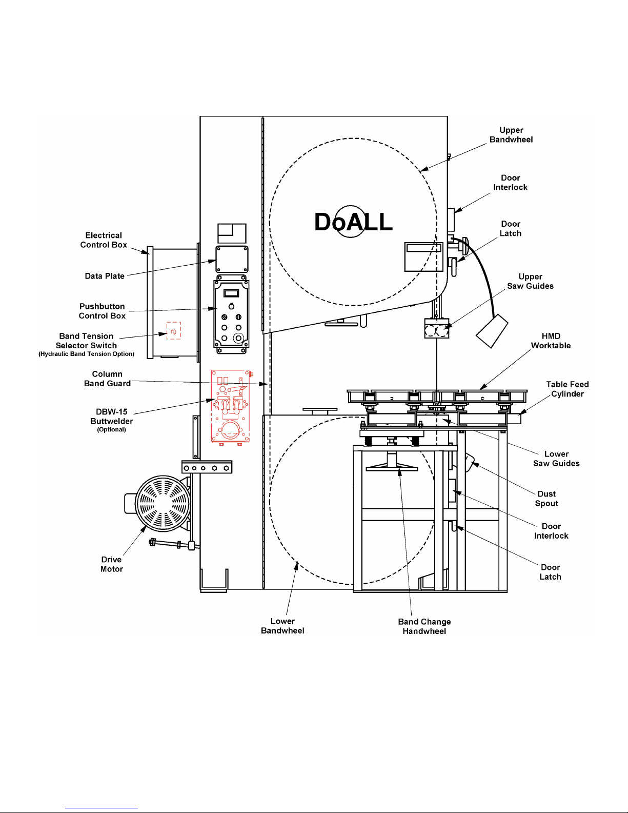
MACHINE FEATURES
FRONT VIEW
6
MACHINE FEATURES (Continued....)
FRONT VIEW With HMD HYDRAULIC TABLE
Indice
Altri manuali DoAll Sega

DoAll
DoAll C-3350NC Manuale utente

DoAll
DoAll 2613-V3 Manuale utente

DoAll
DoAll C-4100NC Manuale utente

DoAll
DoAll 500SNC Manuale utente

DoAll
DoAll c-530 nc Manuale elenco delle parti

DoAll
DoAll C-8056SA Manuale utente

DoAll
DoAll C-260 NC Manuale elenco delle parti

DoAll
DoAll c-530 nc Manuale utente

DoAll
DoAll C-520NC Manuale utente

DoAll
DoAll TF-2525 Manuale utente

DoAll
DoAll 3613-V5 Manuale utente

DoAll
DoAll C-820 M Manuale elenco delle parti

DoAll
DoAll 800SNC Manuale utente

DoAll
DoAll DS-320SA Manuale utente

DoAll
DoAll C-530 M Manuale tecnico di riferimento

DoAll
DoAll 800SNC Manuale utente

DoAll
DoAll C-916S Manuale utente

DoAll
DoAll C-4033NC Manuale utente

DoAll
DoAll C-260 NC Manuale elenco delle parti


