Downee Spring Gate Manuale

All business
No bullsh*t
All business
No bullsh*t
SOLAR PANELSUPDATE
January 2016
Late in 2015 our specialist solar panel supplier closed
without notice. Since then all Sprint Gate Solar kits are
supplied with double panels.
This wiring diagram shows how to connect the double
panels.
Red
Red
Red
Black
Black
Black

All business
No bullsh*t
20/01/16
All business
No bullsh*t
INSTALL
MANUAL
SPRINT GATE SOLAR
DOUBLE GATES
Read this manual before starting install
IMPORTANT

WELCOME!
Fed up with all the uff found in manufacturer’s instructions? The backbone
of Short Cuts manuals is short and snappy info to get the best results fast.
Produced in-house by the team at Downee, Short Cut manuals are created
using plain English and our own real-world install experiences. We’ve chopped
off the fat leaving only the meaty bits you need to get a gate system rocking in
record time.
Don’t feel like reading? No worries! Video versions of Short Cut manuals are
in the Tech Area page for this motor on our website.
TROUBLESHOOTING 1800 241 733
Call our Tech Team
INDEX PAGE
Gates
Motor Position
Brackets
Battery Box
Solar Panel Post
Solar Panel
Stop Limits
Power Up Motor One
Connect Motor Two
Programming
Connect the Remote
Connect the Aerial
Accessories
Solar Controller
2
2
3
4
4
5
5
6
7
8
9
9
10
11
Video instructions of
this manual are on
our website.

KIT
PARTS
1
Panel
Post
5
1 2
3
4
8
5
7 7
6 6
Gate Bracket
and Clamp
7
Post
Bracket
6
1
NOT SUPPLIED
- Angle Brackets for
Battery Box
- Gate Post Cap for
Panel Post
- Tek Screws
- 2-Core Cable
8
Solar
Controller
12V 22Ah
Batteries
Battery Box
with high
security key
Black Max
Remotes
3
Booster
Aerial
30W Solar
Panel
4
2
Motor Two
24V Motor
Motor One
24V Motor with
Control Board
1

GATES
Check gates are in excellent operating condition. Gates in poor operation will
give you trouble and prematurely wear out.
1. Close the gates.
2. Extend Motor Arms.
3. Hold Motor on the gate post where the Arm meets the Gate Stay.
If there’s no stay, mount on the gate frame.
4. Mark the posts at the bottom of the Motor.
TIPS
A
B
These steps apply to both motors
Best position for a Motor is halfway up the Gate Post.
MOTOR POSITION
CODE: S8-AT
CODE: G7-BBAT
DELUXE HINGES
Gates with automation need heavy duty hinges
to handle the load. Designed for Sprint Gate,
Deluxe bearing hinges are the nest farm
gate hinges available anywhere.
2
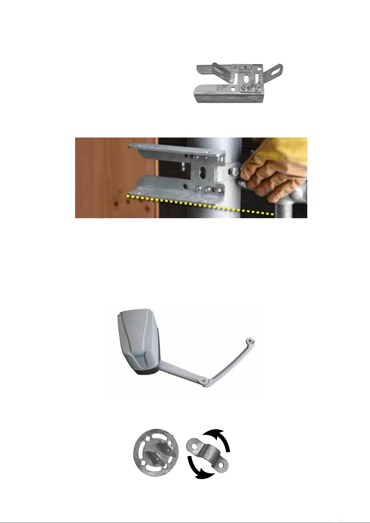
1. Adjust the Post Brackets to t the
Gate Post width and tighten.
2. Mount Post Bracket with bottom edge on the mark. (#4 previous page)
3. Remove a Top Cover off a motor to nd which one houses the
electronic Control Board.
4. Bolt both Motors to Post Brackets
5. Bolt the Arms to Motors. Pin the thin arm Arm onto the thick arm.
The thin arm ts left or right hand gates.
6. Pin the Universal Gate Bracket to the Thin Arm and mount
it to the gate stay. The bracket clamp rotates to t any angle.
BRACKETS
GATE THIS
SIDE >>>>
3

BATTERY BOX
SOLAR PANEL POST
1. Work out where the Battery Box will sit above Motor One.
2. Start with the bottom Post Bracket and mount it
to Gate Post.
3. Attach the other angle bracket to the top
mount on the battery box. Sit the Box on
the bottom angle and attach the top angle
to the Gate Post.
4. Use the key to open the box and remove the foam blocks.
1. Drill a hole in the centre of the post cap and bolt it
onto the Panel Post.
2. Place the Cap & Post onto the top of the gate post.
It may be a tight and may need some gentle
encouragement with a hammer. Keep it in place
with self tappers or tek screws.
Steel Post Cap not supplied in this kit. Measure the
diameter of your gate post to match a Post Cap.
Position the bolt holes east-west for the solar panel to face north. Not
sure which direction north sits? Download a free compass app onto
your smart phone.
Keep the carton containing the solar panel in good condition. You’ll
need it a bit later.
NOTE
TIP
NOTE Post Brackets are not supplied with Sprint
Gate Kits. Two pieces of angle will do.
4

1. Using Tek screws mount Panel Bracket to the
Solar Panel.
2. Tek screw the Aerial on top of the Solar Panel Frame.
3. Bolt the Solar Panel (facing north) to the Panel Post. Leave the carton
covering the Panel.
TIP If the gate is shaded through the day, position the Solar Panel away
from the gate.
Setting the solar panel’s angle to suit the location
will give maximum charging rate.
PANEL ANGLE
STOP LIMITS
1. Use the Motor Key to unlock the Motor Arm.
2. Close the gate. Bolt a Stop in place where
the Arm will sit against it when closed.
3. Open the gate and add a Stop for the
gate’s open position.
4. Adjust as needed then tighten all bolts.
SOLAR PANEL
90
0
80
70
60
50
40
30
20
10
Adelaide 34˚
Perth 31˚
Brisbane 27˚
Darwin 12˚
Tasmania 40˚
Melbourne 38˚
Sydney 35˚
Canberra 35˚
Stop
5
Key

POWER UP MOTOR ONE
1. Remove the Motor cover and the inner control
board cover.
2. Use a screwdriver to punch a hole in the cable
entry point provided (right).
3. Run the battery cable from Battery Box to motor via the new hole.
Then divert wire to left side through the hole used to route wires in
the grey plastic base.
4. Strip the ends of the brown & blue
wires (white outer cable).
5. Remove two black wires from
the 22VAC INPUT terminals
and pull them through and
out of the way.
6. Connect the brown & blue
wires from the battery into
the 22VAC INPUT terminals.
Bottom View
Control Board
22VAC
INPUT
6

1. Dig a channel for Conduit.
2. Run the Figure 8 cable
through Conduit.
3. Connect Figure 8 cable to red
& blue cables on both Motors.
4. Place the fuse (inside Battery Box door) into the fuse holder on the red
power cable. The batteries are fully charged so it may spark. That’s OK,
24V is completely safe.
5. With the carton still covering the solar panel, connect the black and red
power cables to the Solar Panel and Battery. The digital screen on
the motor’s control board and solar controller screen will light up.
6. Cable tie the power cables to the post.
Use 0.75mm Figure 8, 2-core cable in conduit buried across driveway
(not supplied). 24V cable is harmless to humans and animals. Bury
conduit at a depth you’re comfortale with.
NOTE
CONNECT MOTOR TWO Red & Blue
Cables
7
Motor One
Indice


