
DUUN VF215 Manuale utente
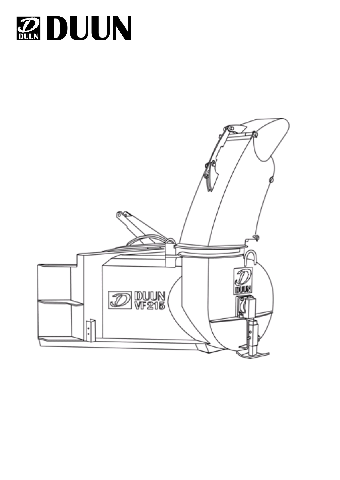
VF215 Instruction manual
Serial number: from 03001
Duun Industrier as
7630 Åsen, Norway
www.duun.no
2
Congratulations on your Duun VF215 snow blower.
All Duun tractor operated machines have been engineered and tested in close cooperation with
representative users to produce functionally safe and user-friendly machines.
Please read this instruction manual before using the machine.
Good luck!
Machine identification
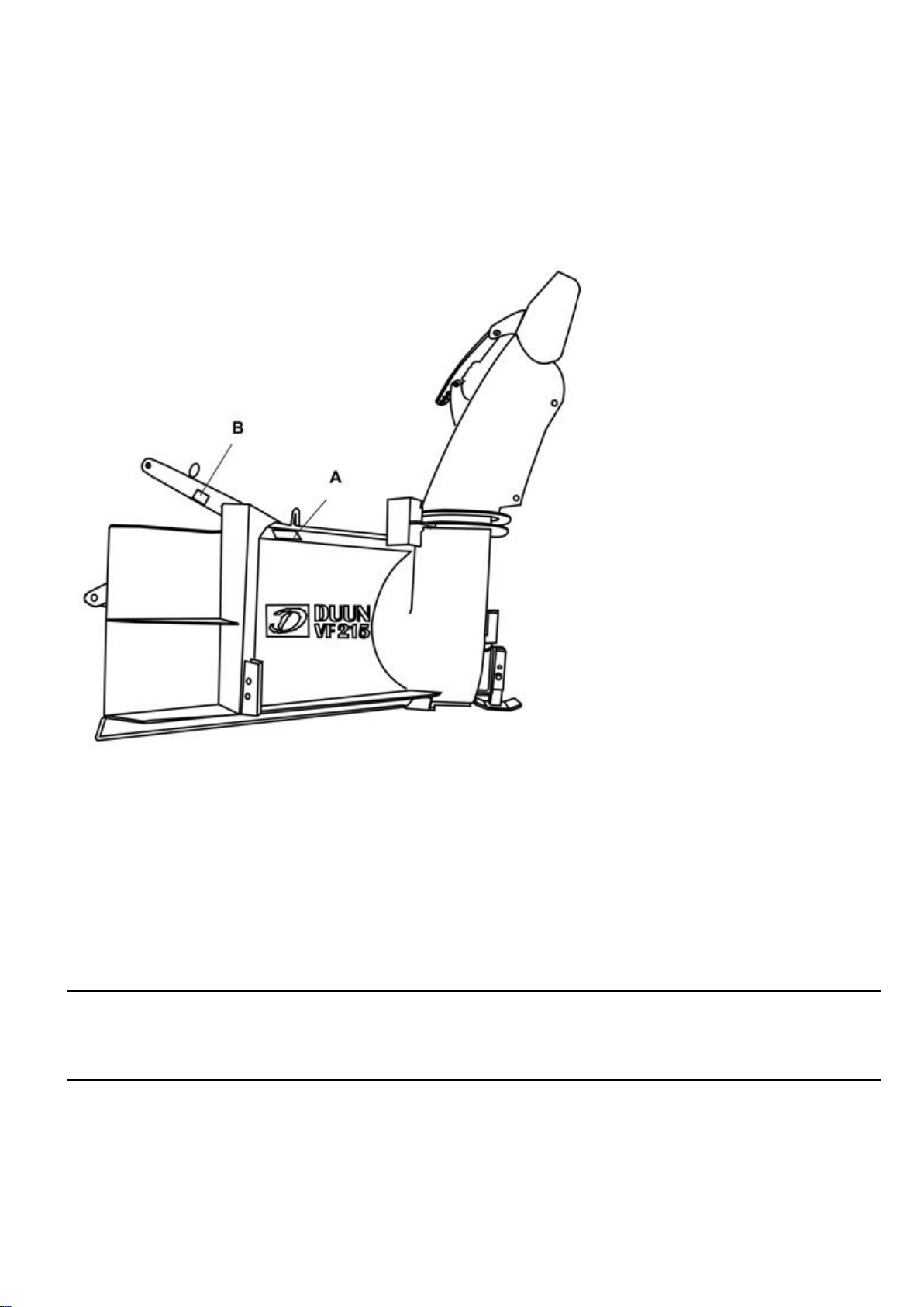
Serial number and manufacturer are indicated on badge (A)
Register serial number and delivery time as indicated.
Always specify serial number when requesting service for the machine.
The machine is CE-marked (B). This marking confirms that the machine has been manufactured
in conformity with EU Directive Machinery.
Serial number
Time of delivery (month/year)

4
SAFETY
All operators, mechanics and the owner must always work carefully with agricultural machinery.
Read and observe safety instructions in this instruction book.
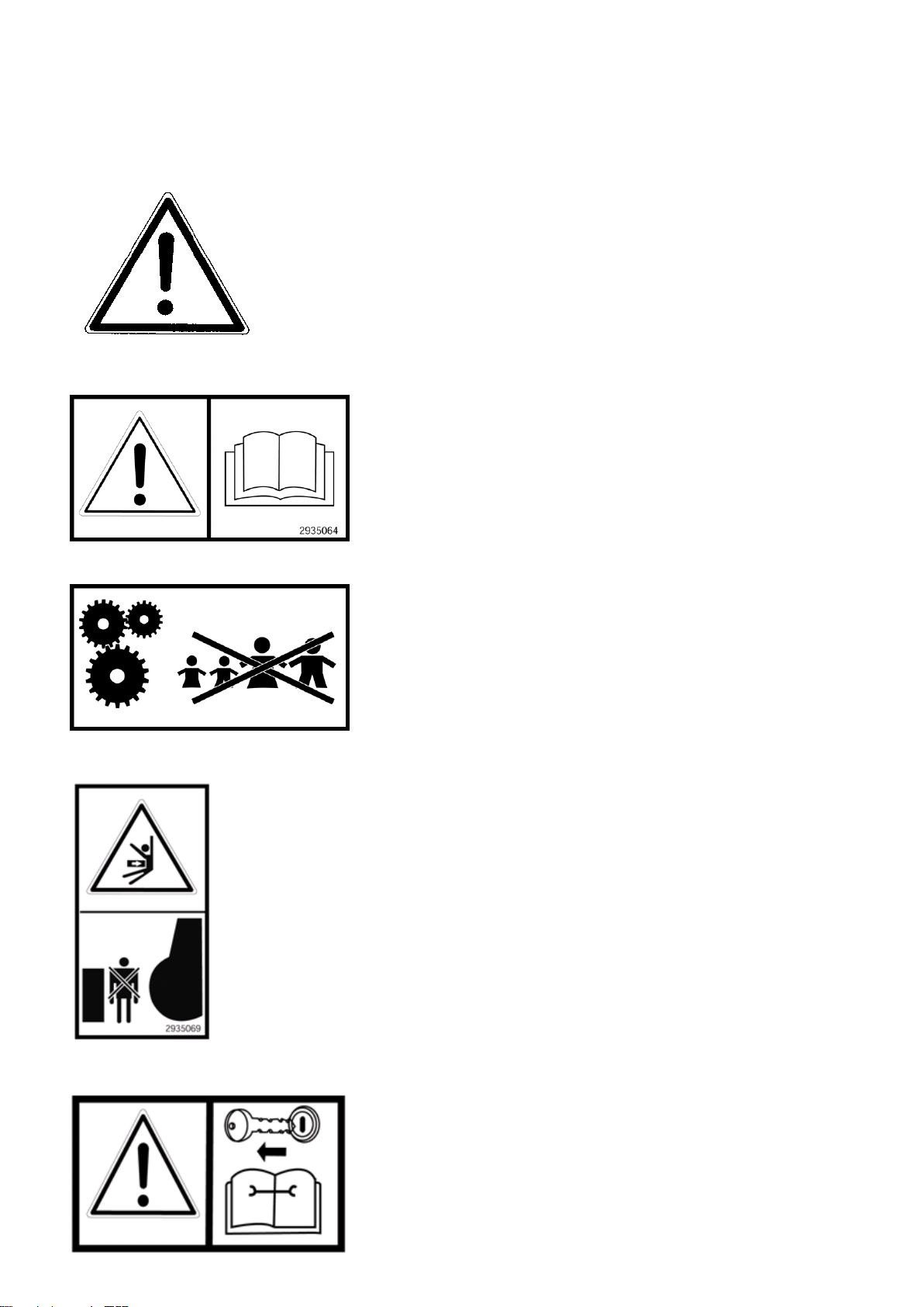
Be particularly aware of warning signs with this symbol, it marks
measures that must be carried out in order to avoid accidents. The
symbol appears in the instruction manual and on warning signs on the
machine.
1. Instruction manual
All operators, mechanics and the owner must be well
acquainted with the instruction in this instruction manual
before the machine is taken into use.
2. Safety of the surroundings
Be very careful when other people or animals are near the
machine or tractor. Never start the machine when there are
people or animals close to it, also never stand between the
tractor wheels and the machine!
3 Safe connection and use
Do not allow anyone to stay between the machine and the
tractor when the machine is connected to the tractor. The
same applies during the use of the machine. Make sure that
the connection is carried out in a safe manner. By
automatically connecting with a triangle or HMV, the
hydraulic hoses are connected before the start of work.
Connecting with draw bolts, secure the drawbar connection
with lunch pins before the hydraulic connection and start
operation.
4. Safety in case of interruptions and maintenance
Remember always to stop the tractor’s engine and remove
the ignition key before you lubricate, adjust, clean, or carry
out repairs. This is to secure that the tractor does not start
before you have completed the operation.
5
5. Power transmission shaft
The tractor is disengaged and the handbrake is applied
before the shaft is connected to the tractor's PTO.
The maximum power output speed is 540 rpm. The drive
shafts are always to be equipped with original protection
covers. Damaged and worn covers are to be replaced
immediately!
Make sure that all covers for the shaft are in good condition
and correctly fitted. Never start the machine when this is not
in order. The locking chains for the plastic covers are
always to be fixed to the appropriate brackets in order to
prevent the covers to rotate. The covers must be lubricated
according to the specified interval.
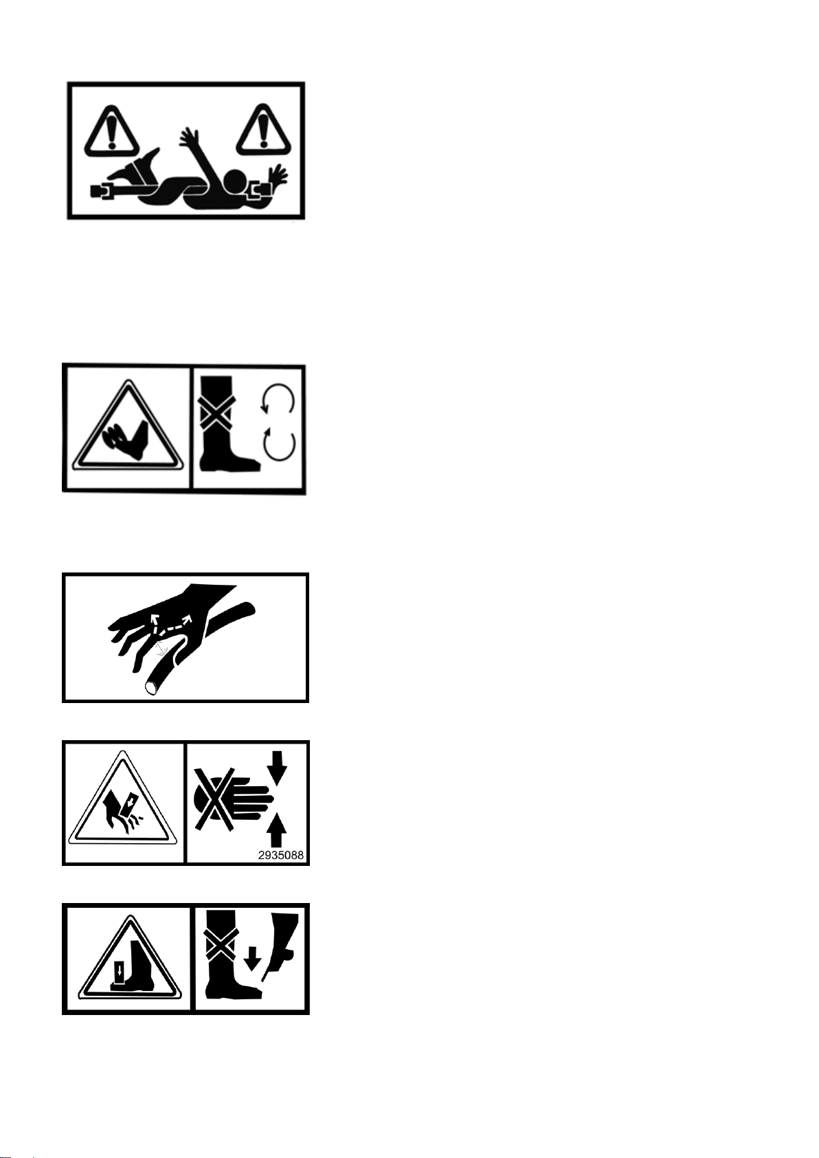
6. Rotating parts –high risk of injury
The rotating parts of the machine can cause major damage
to body parts that come into contact with them. Do not allow
anybody to stay in the work area when a machine is in
operation.
7. Hydraulic high fluid pressure
Be careful when you work with hydraulics. Wear eye
protection and gloves. Hydraulic oil under high pressure
may penetrate the skin and cause serious infections. See a
doctor if you have sustained an injury. Make sure no one is
close by when performing hydraulic functions.
8. Risk of crushing at marked points
Pay special attention to clamping risk at points marked for
this.
9. Clamping risk when adjusting
When adjusting the support wheels, make sure that you do
not stand with your feet under the wear steel.

6
Always lower the machine to safety rest at ground level when it needs to be parked.
Never work under a lifted device unless it is mechanically secured against coming down.
Before startup after servicing make sure all tools have been removed and brought into place.
Do not work in clothing that can be retracted into moving parts of the machine (e.g. scarves, wide
coats).
Wear hearing protection if the machine has annoying or damaging noise levels.
Before the machine is raised or lowered, make sure that no person is near or touching the
machine.
If warning signs are removed during repairs or service, new signs should be installed
immediately!

7
Warranty terms
Duun VF215 has 12 months guarantee against defects in materials and workmanship.
Parts that are not originally manufactured by Duun Industrier as, for example, wheels, hydraulic
parts, etc. are subject to these suppliers’ guarantees and terms.
In cases where a repair is considered to be covered by the guarantee, the representative must
inform the supplier’s representatives that the repair is intended executed based on the guarantee.
In this context, the following information must be recorded:
•Product name
•The product’s serial no. (see the machine identification)
•Date of sale
•The product owner’s address, telephone no.
In case of such a repair, the supplier is presented with a claim within 3 weeks after the repair date.
Replaced parts are to be kept until a decision has been made with reference to the claim and the
replaced parts are to be forwarded to Duun Industrier as for assessment if so required.
As the employment of the product is beyond our control, we may only guarantee the quality and
do not accept liability for the product's general performance.
Duun Industrier as reserves the right to modify the design and specifications and/or make
alterations and improvements without notification.
What is not included in the guarantee:
•The guarantee does not cover economic loss as a consequence of interruptions.
•The guarantee does not cover consequential loss due to defects.
•The guarantee does not cover defects or damage caused by misuse and uses that are not
in accordance with the instruction manual’s specifications and guidelines.
8
Technical data

9
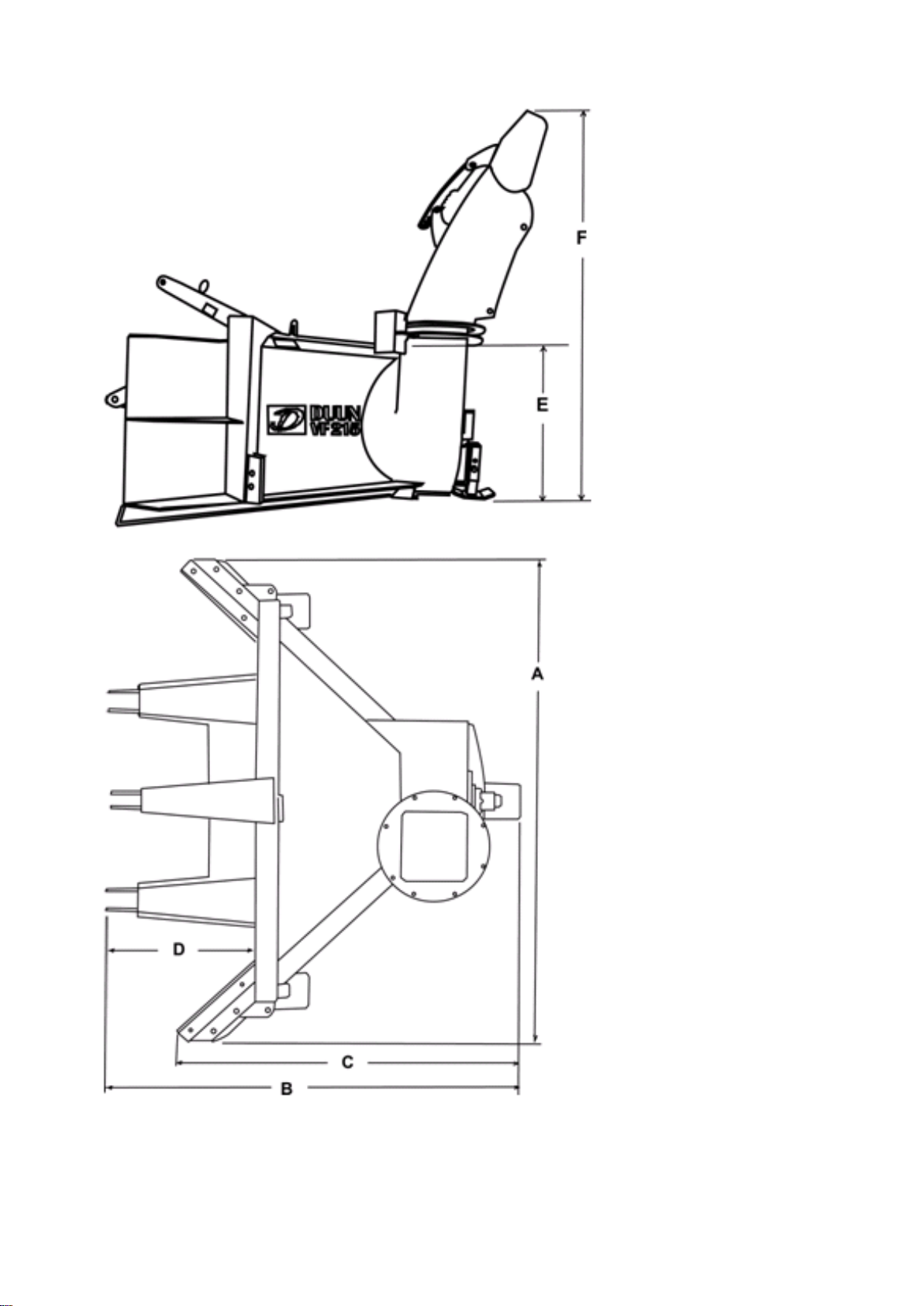
Features:
VF215
Weight
450 kg
Width (a)
2150 mm
Maks lengde (b)
1830 mm
Side length (c )
1510 mm
Three-point linkage (d)
655 mm
Working height chassis (e)
800 mm
Max height of outlet spout (f)
1955 mm
Speed of PTO shaft
540 rpm
Bolt fasteners connections are
standard
Yes
Number of blades in ejector fan
4
Diameter of fan
700 mm
Power requirement PTO
55hk/40kw
Diameter of right side wear steel
10x100x1310mm
Diameter of left side wear steel
10x100x1310mm
Fastening wear steel.
305 mm
Asseccories:
Side extension 1m right 1251315
Yes
Side extension 1m left 1251316
Yes
Extra set (pair) of skid pads 1251317
Yes
Hydraulically operated outlet flap
1251118
Yes
PTO
Yes
Triangle coupling 1252637
Yes
HMV coupling 1252638
Yes
10
Transportation and
management before use
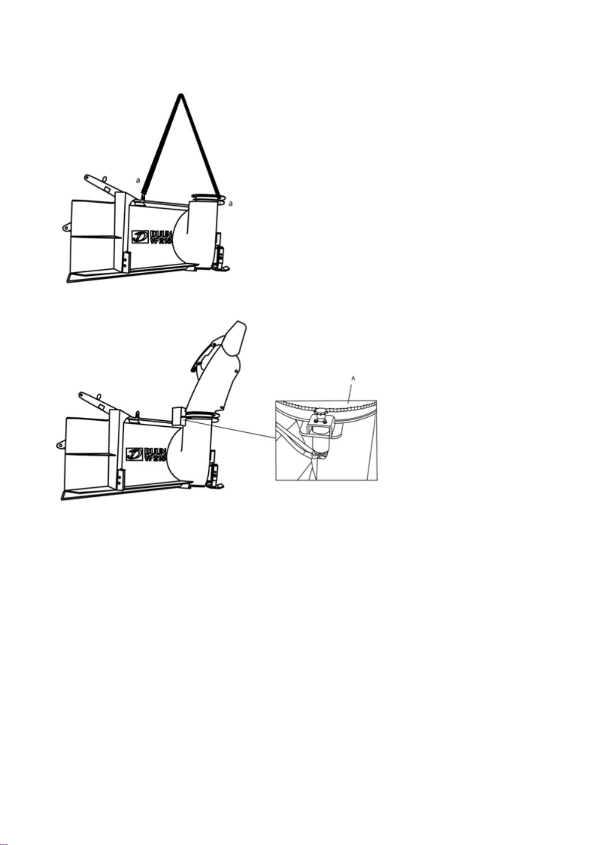
Snow blower housing is always
lifted with strap attachments as
illustrated. Please note that a
single snowblower weighs is
approx. 450 kg. Use lifting
equipment suitable for this
weight!!
Installation of the ejector
spout and drive motor
Bracket with oil motor is
unscrewed by loosening 2
pieces of M10 screws. The
ejector spout is attached to the
hull with 6 m10 screws, washer
and lock nut for this. The
bracket with the oil motor is
fixed in place, the adaptation of
this to the "tooth ring" is
adjusted with the fastening
screw A. It is adjusted so that
the spout can rotate easily
(clearance approx. 1mm).
Questo manuale è adatto per i seguenti modelli
1
Indice
Altri manuali DUUN Spazzaneve


