Dynon D180 FlightDEK Manuale utente

J7886 D180 v1.1 Page 1 of 20
Dynon D180 FlightDEK Reference Manual
This manual contains information for the use of the Dynon D180
FlightDEK as configured for Jabiru 24-7886.

J7886 D180 v1.1 Page 2 of 20
Contents
1 Important Note................................................................................................................................... 3
2 Definitions ......................................................................................................................................... 3
3 Overview & Basic Operation .............................................................................................................. 4
3.1 Power ......................................................................................................................................... 4
3.2 Front Panel Layout ..................................................................................................................... 4
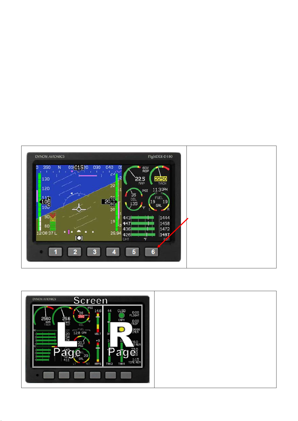
3.3 Screens and Pages .................................................................................................................... 4
3.4 Cycling Screens ......................................................................................................................... 5
3.5 Menus ........................................................................................................................................ 5
3.6 Menu Functionality ..................................................................................................................... 5
3.7 Menu Flows ................................................................................................................................ 6
3.8 Alerts .......................................................................................................................................... 6
3.8.1 Alarm Indicators .................................................................................................................. 6
3.8.2 SHOW PAGE ...................................................................................................................... 6
3.8.3 ALARM SILENCING ............................................................................................................ 7
3.8.4 ALARM ACKNOWLEDGE ................................................................................................... 7
3.8.5 Latching and Self-clearing Alarms ....................................................................................... 7
4 Screens ............................................................................................................................................. 8
4.1 EFIS Main Page ......................................................................................................................... 8
4.1.1 BARO – Changing Altimeter Setting .................................................................................... 9
4.2 AUX Page ................................................................................................................................ 10
4.3 EMS Page ................................................................................................................................ 10
4.4 TIMES Page ............................................................................................................................. 11
4.5 EMS FUEL Computer Page ..................................................................................................... 11
4.6 HSI Page .................................................................................................................................. 12
5 Autopilot Operation .......................................................................................................................... 13
5.1 EFIS AP Menu and Displays .................................................................................................... 13
5.1.1 EFIS AP Menu and Status ................................................................................................. 13
5.1.2 Bugs Display ..................................................................................................................... 13
5.1.3 Bugs Graphical Appearance .............................................................................................. 13
5.2 AP Modes ................................................................................................................................ 14
5.3 EFIS Autopilot Control .............................................................................................................. 14
5.3.1 Mode -(H, T, or N) ............................................................................................................. 14
5.3.2 (HDG, TRK or NAV) OFF/ON ............................................................................................ 15
5.3.3 ALT OFF/ON ..................................................................................................................... 15
5.3.4 180 .................................................................................................................................... 15
5.3.5 BUGS ................................................................................................................................ 16
5.3.6 Out of Trim Indicator .......................................................................................................... 16
5.4 AP74 Autopilot Control ............................................................................................................. 17
5.4.1 AP74 Indicators ................................................................................................................. 17

J7886 D180 v1.1 Page 3 of 20
5.4.2 AP74 Controls ................................................................................................................... 17
5.5 HSI - GPS Overlay ................................................................................................................... 19
1 Important Note
The Dynon D180 FlightDEK is an instrument that is configurable for many different aircraft and engine
types. It is also capable of managing inputs from a variety of optional sensors.
Whilst this aircraft has had the EFIS customised on installation, it is still possible for a user to actively or
inadvertently alter many of the settings. Care must be taken to avoid this. At best, another pilot may not
be able to access key information, and at worst, may result in the aircraft being inoperable until we can
engage a professional to reset the EFIS at our cost.
Please report immediately if you think that some aspect of the EFIS operation does not meet the directions
given in this guide.
2 Definitions
EFIS Electronic Flight Information System
EMS Engine Management System
HSI Horizontal Situation Indicator

J7886 D180 v1.1 Page 4 of 20
3 Overview & Basic Operation
It is essential that all pilots of 7886 are familiar with the overview and basic operation of the D180.
Operation of advanced features, and the Auto-pilot, are only required for pilots wishing to utilise these
features.
3.1 Power
The D180 will power up when the master switch is turned on. It is acceptable to have the D180 on during
engine crank.
Power On – Press button 1.
Power Off – Press and hold button 1 until the display turns off.
3.2 Front Panel Layout
The display is set up to provide all
necessary flight information.
The buttons are used to turn the
instrument on and off, cycle
between screens, scroll through
menus, and adjust instrument
parameters
3.3 Screens and Pages
Screens contain one or two pages and pages
contain groups of similar information.
A page is a section of the screen that contains
a collection of related data. Pages share the
screen with other pages (2/3, 1/3 split).

J7886 D180 v1.1 Page 5 of 20
3.4 Cycling Screens
Buttons 1 and 6 cycle to the
previous and next screens,
respectively.
3.5 Menus
On a screen where no menu is already present,
buttons two through five are used to display a
menu.
All of the default screens are divided into two
pages with the left page occupying 2/3 of the
screen and the right page occupying 1/3 of the
screen.
Pressing buttons two, three, or four (all below the
left 2/3 of the screen) displays the main menu for
the left page and pressing button five (below the
right 1/3 of the screen) displays the main menu
for the right page.
3.6 Menu Functionality
A menu consists of two rows of gray boxes
containing text. The upper row contains one
tab that denotes the currently displayed
menu. The lower row contains six labels that
denote the function of the button below it.
Many of the onscreen elements move up to
avoid the menu. This prevents the menu
from obscuring useful data while it is up.
Upon exiting the menu, the screen returns to
its normal appearance.
Pressing a button either displays another
menu or adjusts a parameter. If there is no
text above a button, then that button does
not have a function in the context of that
menu. Occasionally, a button label spans

J7886 D180 v1.1 Page 6 of 20
two or more buttons. In this case, any button
below the label invokes the command.
If a menu contains more options than there
are buttons, the MORE label is displayed
over button five. Pressing this button shows
you the next set of options in the current
menu.
In any menu, press the BACK button to
return to the previous menu and save any
changes. In all top-level menus, button six is
the EXIT button. Pressing EXIT removes the
menu system and moves many of the
onscreen elements down to their original
positions.
3.7 Menu Flows
Each page has its own main menu, which
may contain options for navigating to other
menus or choosing and adjusting
parameters.
For example, the EFIS Main Page menu
contains an EFIS menu tab and button
labels for MENU►, BARO, AP, LISTS,
MORE, and EXIT.
Pressing MORE reveals the rest of the EFIS
menu. This menu contains options for
SETUP, INFO, DIM, TIMER, MORE, and
EXIT. Pressing MORE on this menu simply
returns you to the first part of the EFIS
menu.
3.8 Alerts
3.8.1 Alarm Indicators
Any time a built-in or preconfigured alarm set point is exceeded, you are alerted via visible alarms.
When an alarm is triggered, the following things occur:
The measurement’s value and tick color are highlighted red
The measurement’s value and tick blink
A red alarm bar appears at the bottom of the screen with a message identifying the out of range
measurement
Below the alarm bar, the alarm menu gives you options for what to do next. See the following
subsections for more information
NOTE:
No audio alert output is fitted to this aircraft so you will not hear an audible alarm.
3.8.2 SHOW PAGE
If the alarming measurement is not displayed on your current screen, or is available on a page which
displays it better, a SHOW [PAGE] button is included in the alarm menu. [PAGE] is replaced with the
name of the actual page that is displayed when you press the button. Press this button to display the
page where the alarming measurement is best displayed. From there, you may press GO BACK to

J7886 D180 v1.1 Page 7 of 20
return to your original screen, leaving the alarm indications active, or press ACK to remove the alarm
and return to your original screen.
3.8.3 ALARM SILENCING
As this aircraft is not fitted with an audible alarm, pressing the SILNCE button has no function.
3.8.4 ALARM ACKNOWLEDGE
To acknowledge the alarm, press the ACK button. The ACK button has a number next to it indicating the
number of currently posted alarms. If this number is higher than 1, after you press ACK the alarm text for
the next posted alarm is displayed in the alarm bar. Pressing ACK does the following:
Removes the alarm bar and alarm menu (if no other alarms are stacked up), and brings up the
previous menu.
Stops the blinking of the relevant display
Returns the display to the screen configuration displayed before the alarm occurred (if you
pressed SHOW [PAGE])
The tic and numeric value remain red until the condition no longer exists. The alarm automatically
rearms whenever the alarm condition is removed.
3.8.5 Latching and Self-clearing Alarms
Alarms may be set to be latching, while others may be self-clearing.
LATCHING ALARMS
If an alarm occurs on a sensor that is latching, the alert displays on screen until the ACK button is
pressed, even if the alarm condition goes away. This means if, for example, your oil pressure
momentarily gets too high but returns to normal, the instrument continues to alarm on the condition until
that alarm is acknowledged. Latching alarms let you to know if an alarm happened momentarily, when
you might have otherwise missed it.
SELF-CLEARING ALARMS
If an alarm occurs on a sensor configured to be self-clearing, the alert displays on screen until either the
ACK button is pressed or the alarm condition goes away. Consider the example where a fuel pressure
alarm to be isself-clearing. If the engine’s fuel pressure momentarily rises too high but then returns to
normal, the D180 alarms for that brief instant, but stops as soon as the alarming condition has ceased;
no acknowledgement is needed.

J7886 D180 v1.1 Page 8 of 20
4 Screens
The screens available in rotation are:
1. EFIS / EMS (boot-up screen)
2. EFIS / AUX
3. EFIS / FUEL
4. EFIS / TIMES
5. EFIS / HSI
4.1 EFIS Main Page
The EFIS screen contains the following:
Horizon line, pitch and roll indicators
(brown/blue at centre of screen)
Heading tape, digital readout and
turn rate indicator (top)
Altitude tape, digital readout, and VSI
(right)
Airspeed tape, digital readout, and
trend (left)
Bugs
Slip/skid ball
Clock (Z indicates Zulu time)
Autopilot Status Indicator
Altimeter barometer setting (bottom
right)
4.1.1 EFIS Voltmeter
The voltmeter displays 3 rows of information
corresponding to the three power inputs:
M – Master switch voltage
E – External backup voltage
I – Internal battery voltage
An alert will be displayed when the iinternal
battery is low.

J7886 D180 v1.1 Page 9 of 20
4.1.2 BARO – Changing Altimeter Setting
Set the primary altimeter to the correct
altitude (eg 110ft at YREN).
Take the pressure reading from the
altimeter.
Select the EFIS BARO option
When the BARO menu is displayed, the
value-setting box shows the current
altimeter setting. The DEC- and INC+
buttons change the altimeter setting by 1
mbar.
Press BACK and then EXIT to exit the EFIS
menu.
The atmospheric pressure reading is
displayed in the lower right of the screen.
NOTE:
The altimeter reading may take a little time
to stabilise after being adjusted.

J7886 D180 v1.1 Page 10 of 20
4.2 AUX Page
This page displays
Voltmeter
Fuel flow
Outside air temperature (OAT)
Timers
Fuel remaining
4.3 EMS Page
This page displays
RPM
oil temperature
oil pressure
cylinder head temperature (CHT)
fuel level
fuel flow
Indice
Altri manuali Dynon Display avionico

Dynon
Dynon SkyView HDX System Guida utente

Dynon
Dynon D3 Manuale

Dynon
Dynon SkyView Classic Manuale utente

Dynon
Dynon EFIS-D10A Manuale utente

Dynon
Dynon D3 Manuale utente

Dynon
Dynon SkyView HDX System Foglio di istruzioni

Dynon
Dynon EFIS-D10A Manuale di istruzioni

Dynon
Dynon SkyView HDX System Specifiche tecniche

Dynon
Dynon D2 Pocket Panel Manuale

Dynon
Dynon SkyView SE Manuale utente
Manuali Display avionico popolari di altre marche

Smart Avionics
Smart Avionics PB-4 Manuale utente

Midcontinent
Midcontinent SAM MD302 Manuale

MGL Avionics
MGL Avionics Stratomaster Maxi Single FF-3 Manuale utente

Garmin
Garmin GI 275 Manuale utente

Mid-Continent Instruments
Mid-Continent Instruments 4300 Series Manuale

Avidyne
Avidyne 700-00182 Series Manuale di servizio


