EarthLinked AVS Series Manuale utente

AVS-410CH-IM (10/13) Copyright 2013 Earthlinked Technologies, Inc.
EarthLinked®
AVS Series Air Handlers
Installation Manual for
R-410A SC and SD Compressor Units in
Heat/Cool or Cool Only Applications
CONTENTS
PAGE
Pre-Installation
3
Electrical Connections and Air Flow 4
AVS Dimensions and Electrical Ratings 6
Thermal Bulb Location and Field Conversion 7
Service Parts 13
Manufacturer’s Installation Instructions 14

AVS-410CH-IM (10/13) Page 2
Disclaimer
Proper installation and service of EarthLinked®Heating and Cooling System Components is essential to
reliable performance. All EarthLinked®components must be installed and serviced by an authorized,
trained technician who has successfully completed the training class and passed the final examination.
Installation and service must be made in accordance with the instructions set forth herein and in the
system installation manual.Failure to provide installation and service by an authorized, trained installer in
a manner consistent with the subject manual will nullify the limited warranty coverage for the system.
READ THE SYSTEM INSTALLATION MANUAL FOR ADDITIONAL DETAILS.
EarthlinkedTechnologies shall not be liable for any defect, unsatisfactory performance, damage or loss,
whether direct or consequential, relative to the design, manufacture, construction, application or
installation of the field specified components.
Earthlinked Technologies, Inc.
4151 South Pipkin Road
Lakeland, Florida 33811
tel. 863-701-0096 ● fax 863-701-7796
info@earthlinked.com ● www.earthlinked.com
CSI # 23 80 00
AVS-410CH-IM (10/13) Page 3
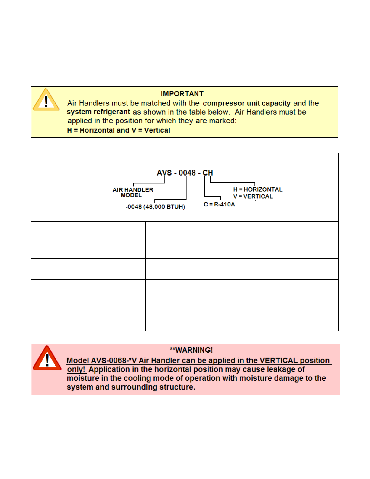
Pre-Installation
These air handlers are for application to Heat/Cool and Cool Only applications!
Upon receipt of the air handler, carefully check the Earthlinked Technologies model number on the
package and on the air handler unit against the air handler model ordered.
AIR HANDLER MODEL MATCH TABLE
AIR HANDLER
MODEL REFRIGERANT POSITION COMPRESSOR UNIT
MODEL/CAPCITY HEATER
KW
AVS – 0024 - CV R–410A VERTICAL -024 (24,000 BTUH)
5
AVS – 0024 - CH R–410A HORIZONTAL
AVS – 0036 - CV R–410A VERTICAL -036 (36,000 BTUH)
10
AVS – 0036 - CH R–410A HORIZONTAL
AVS – 0048 - CV R–410A VERTICAL -048 (48,000 BTUH)
15
AVS – 0048 - CH R–410A HORIZONTAL
AVS – 0060 - CV R–410A VERTICAL -060 (60,000 BTUH)
20
AVS – 0060 - CH R–410A HORIZONTAL
AVS – 0068 - CV R–410A VERTICAL -068 (68,000 BTUH) 20
If it is necessary to change the installed position of the air handler in the field, the conversion process is
described in this manual under Thermal Bulb Location and Field Conversion.

AVS-410CH-IM (10/13) Page 4
AVS Electrical Connections and Air Flow
The variable speed AVS Series air handler control board and field wiring diagram are illustrated in
Figure 1.
Figure 5. AVS Series Air Handler Control Panel and Field Wiring
The blower speeds can be adjusted by changing the jumper settings on the control board as appropriate.
Heat and Cool panels: “A” is the highest speed and “D” is the lowest speed.
Adjust panel: “NORM” is the normal airflow. “+” is more airflow. “-“ is less airflow.
Test panel: NOT FOR FIELD ADJUSTMENT. FOR FACTORY USE ONLY.

AVS-410CH-IM (10/13) Page 5
Model Number Jumper CFM @
0.10” CFM @
0.20” CFM @
0.30” CFM @
0.40” CFM @
0.50”
AVS-0024-C*
A 839 832 818 811 801
B 743 728 716 712 704
C 704 688 679 672 663
D 628 619 610 596 586
AVS-0036-C*
AVS-0048-C*
AVS-0060-C*
A 1957 1919 1900 1871 1947
B 1576 1565 1547 1517 1487
C 1495 1482 1451 1432 1409
D 1411 1385 1372 1338 1311
AVS-0068-CV
A 2393 2393 2393 2393 2388
B 2227 2227 2221 2221 2221
C 2012 2012 2005 2005 2005
D 1795 1795 1795 1795 1795
AVS-0068-CV
(“+” adjustment)
A 2481 2481 2475 2464 2417
B 2441 2441 2441 2435 2399
C 2327 2327 2327 2321 2315
D 2081 2081 2081 2081 2075
Figure 6. AVS Series Variable Speed Air Handler – Air Flow

AVS-410CH-IM (10/13) Page 6
AVS Dimensions and Electrical Ratings

AVS-410CH-IM (10/13) Page 7
Figure 7. AVS Series Variable Speed Air Handler Dimensions and Electrical Ratings.
Thermal Bulb and Field Conversion
The air handler is shipped from ETI as it was ordered, either for vertical or horizontal installation. Figure 8
illustrates an air handler shipped from the factory with the TXV thermal bulb attached to the suction tube.
Figure 8. Air Handler and Thermal Bulb as shipped

AVS-410CH-IM (10/13) Page 8
The thermal bulb must be located and clamped to a HORIZONTAL extension of this suction tube,
with options for the suction tube extension illustrated in Figure 9. This shows the suction tube directional
options for an air handler that is to be installed in the VERTICAL direction.
Figure 9. Horizontal Suction Line Options – VERTICAL Air Handler Installation

AVS-410CH-IM (10/13) Page 9
Figure 10 illustrates locating the thermal bulb on the suction line extension. It shall be located at least 6
inches downstream of any fitting or bend in the suction tube extension, and at the 3:00, 4:00, 8:00 or
9:00 o’clock positions.
Figure 10. Positioning the Thermal Bulb

AVS-410CH-IM (10/13) Page 10
Clamp the thermal bulb firmly against the clean suction tube extension and parallel to it, as shown in
Figure 11, to ensure good thermal contact along the entire length of the thermal bulb.
Figure 11. Clamp the Thermal Bulb to the Suction Line Extension
Questo manuale è adatto per i seguenti modelli
9
Indice


