
ECH2O Tec. Watermakers 200-BMS-1 Manuale utente

E
EE
E
C
CC
C
H
HH
H
2
22
2
O Tec.
O Tec.O Tec.
O Tec.
TM
Watermakers
MODULAR SERIES (BELT DRIVEN)
200-BMS-1 / 400-BMS-2 / 500-BML-1
600-BMS-3 / 800-BMS-4 / 900-BML-2
1200-BML-3 / 1500-BML-4
OWNERS MANUAL
Pages
2 INTRODUCTION
3 SPECIFICATIONS
4-5 STANDARD SYSTEM FEATURES, OPTIONS AND ACCESSORIES
6 FLOW DIAGRAM
7- INSTALLATION INSTRUCTIONS
10 INSTALLATION INSTRUCTIONS OPTIONS
11-13 SYSTEM OPERATION, SHUT DOWN AND FLUSH PROCEDURE
14 MAINTENANCE TIMETABLE
15 MEMBRANE VESSEL ENDPLUG CHANGING PROCEDURE
16 TROUBLESHOOTING GUIDE
17-1 HIGH PRESSURE PUMP REPAIR INSTRUCTION
20-21 WARRANTY

INTRODUCTION
Thank you for choosing an ECH
2
O Tec. reverse osmosis watermaker. We trust that you will be
completely satisfied with our product.
ECH
2
O Tec Watermakers are manufactured by Echo Marine as a result of many years of
experience installing, servicing and modifying all brands of watermakers. Only highest quality
components that have proven to withstand continuous duty in a harsh marine environment are
selected for ultimate reliability and lifetime.
We thoroughly bench test every single watermaker before shipping and feel we have
manufactured one of the finest products on the market.
The purpose of this manual is to allow you to become familiar with each component of your
new ECH
2
O Tec. Watermaker.
By understanding the function, importance and normal operation of each part in the system, the
operator can readily diagnose problems when they first develop. Such problems are easily
corrected and require minor adjustments. If left unattended, a small problem in one component
will affect the rest of the system and can lead to an expensive repair.
If you have any questions regarding the installation or operation of your watermaker please
contact us. We are happy to assist you.
ECHO MARINE LTD.
1st Avenue South,
Chaguaramas
Trini a W.I.
TELEPHONE: 1-868-634-2027
FAX: 1-868-634-2026
E-MAIL: echotec@echo-marine.com
www.ech2otec.com

SPECIFICATIONS (BELT DRIVEN)
RATED PERFORMANCE:
ECH
2
O Tec. 200 – BMS-1 8 gallons / 30ltr. / hour
400 – BMS-2 16 gallons / 60ltr. / hour
500 – BML-1
20 gallons / 76ltr. / hour
00 – BMS-3 24 gallons / 90ltr. / hour
800 – BMS-4 33 gallons / 126ltr. / hour
900 – BML-2
38 gallons / 143ltr. / hour
1200 – BML-3 50 gallons / 190ltr. / hour
1500 – BML-4 60 gallons / 230ltr. / hour
Reverse Osmosis performan e varies with the feed water temperature and salinity.
The rated performan e is tested at 26°C / 80°F water temperature and 33g NaCl/ltr.
RO MEMBRANE TYPE:
Standard size high reje tion TFC Polyamide, thin film omposite, spiral
wound, single pass reverse osmosis element.
PRODUCT WATER QUALITY: minimum 500 ppm TDS
FEED WATER SALINITY RANGE: up to 50,000 ppm TDS (NaCl)
PH RANGE: 4 – 11
CHLORINE TOLERANCE: 1000-ppm hours
FEED WATER PRESSURE: 5”Hg to 60 psi
OPERATING PRESSURE: 800 to 900 psi
FEED WATER TEMPERATURE RANGE:
Min. 33°F / 0.5°C, max 113°F / 45°C
ELECTRICAL POWER REQUIREMENTS: 12V DC / 4A
HIGH PRESSURE PUMP FLOW/RPM:
Model EP-12-34: 2.8 gal/min. @ 1050 RPM – 3.9 gal/min. @ 1450 RPM

STANDARD SYSTEM FEATURES
1) 1 PVC sea strainer
2 3/4” barbed hose connectors straight
2) 1 Filter housing with 20 micron pre filter cartridge (without boost pump) or
2 Filter housings with 5 and 20 micron pre filter cartridges (with boost pump)
1 Stainless steel bracket with 8 screws.
1 20micron cartridge
1 1/2” Service valve with 1 Nylon nipple and 3 barbed hose connectors (with boost pump)
or
1 3/4” flush/storage valve with 1 Nylon nipple and 1 NPT female tee (without boost pump)
1 Filter wrench
3) 1 High-pressure pu p with stainless steel pump head and magnetic clutch
4) Pressure vessel(s) with reverse os osis e brane(s)
500 BML1 One 40” vessel
900 BML2 Two 40” vessels
1200 BML3 Three 40” vessels
1500 BML4 Four 40” vessels
5) 1 Stainless steel control panel
1 Stainless steel self regulating pressure control valve
1 High pressure gauge
1 Product flow meter (25 / 50 / 100gph)
1 Diverter (3 way) valve
1 Breaker (10amp) or
2 Breakers (10 amp with optional boost pump)
6) 1 Hardener / pH neutralizer kit with mineral element and 2pcs 3/8” compression fittings
1 Stainless steel bracket with 8 screws
7) 15 feet / 4.5 meter high pressure hose with 2 x stainless steel high pressure fittings attached
2 Stainless steel field attachable high pressure fittings
8) 20 feet / 6 meter 3/8” blue product water tubing or 1/2” braided hose (model 1500)
10 feet / 3 meter 3/4” wire coil reinforced hose (without boost pump only)
10 feet / 3 meter 1/2” braided reject hose
9) 2 x 1/2” stainless steel hose clamps (model 500, 900, 1200) or
6 x 1/2” stainless steel hose clamps (model 1500)
6 x 3/4” and 2 x 5/8” stainless steel hose clamps (with boost pump) or
8 x 3/4” stainless steel hose clamps (without boost pump)
10) 1 Handheld TDS Meter
2 Filter cartridges, 20 microns (without boost pump) or 5 and 20 microns (with boost pump)
1 Biocide, 1 acid cleaning solution, 1 alkaline cleaning solution

AVAILABLE OPTIONS AND ACCESSORIES
If the high pressure pump is installed less than 1 foot under the waterline or an
additional 5 micron pre filter is added, the installation of an optional boost pump is
recommended.
Boost pu p (3/4” intake hose barb, 5/8” outlet hose barb, 4 feet / 1.2 meter 3/4”
wire reinforced intake hose, 10 feet / 3 meter 5/8” braided feed hose)
Fresh water flush kit with boost pu p (filter housing, charcoal cartridge, stainless
steel bracket, 8 screws, shut off valve, 2 x 5/8” hose barb connectors, 5/8” tee, 10ft
5/8” braided hose, 6 x 5/8” hose clamps)
Fresh water flush kit without boost pu p (filter housing, charcoal cartridge,
stainless steel bracket, 8 screws, shut off valve, 2 x 5/8” hose barb connectors, 10ft
1/2” braided hose, 4 x 1/2” hose clamps)
Low pressure gauge
The low pressure gauge indicates when the pre filters have to be changed.
An additional 5 micron pre filter is only recommended in connection with the
optional boost pump
5 Micron Pre-filter Housing (1 filter housing, 1 pre filter cartridge, 1 bracket, 1
3/4” NPT nipple)
Note: The 5micron filter has to be installed as a second filter in flow direction
Maintenance Kit
10 Pre filters, 5 and/or 20 microns
1 Spare sea strainer screen
2 Active carbon filters (fresh water flush)
1ltr. High pressure pump oil
Extended Maintenance Kit
1 Acid cleaning compound
1 Alkaline cleaning compound
2 Storage compounds (Biocide)
1 Complete spare seal and O ring kit (except high pressure pump)
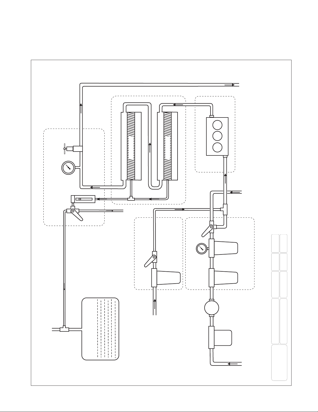
FLOW DIAGRAM WITH OPTIONS
CONTROL PANEL
FRESH WATER OUTLET
EXSISTING
FRESH WATER TANK
FRESH WATER INTAKE
SEA WATER INLET
SYSTEM
MODULAR-SERIES
ECH O Tec.
2
Watermakers
DATE
31/05/06
REV.
3.1
DRWN
MS
BOOST PUMP
FRESH WATER FLUSH FILTER
FILTER
STRAINER FILTER
PUMP FILTER
5µ
20µ
PSI
PSI
FLOW REJECT WATER
REJECT WATER OUTLET
CLEANING / STORAGE
SOLUTION INTAKE
R.O. MEMBRANE VESSEL RACK
MEMBRANE
MEMBRANE
HIGH PRESSURE PUMP UNIT
PRESSURE
CONTROL
VALVE
SAMPLE
OUTLET
LOW PRESSURE GAUGE
HIGH PRESSURE GAUGE
PRE-FILTRATION SYSTEM

INSTALLATION INSTRUCTIONS (BELT DRIVEN)
HIGH PRESSURE PUMP
To minimize vibration, it is best to build brackets on the motor itself, similar to alternator brackets. Use
cardboard to construct a pattern first before making these brackets.
The high-pressure pump has a maximum RPM of 175 . The recommended working RPM is 450.
Minimum RPM for ECHO Tec. watermaker models: 200 - 500: 900 RPM
600 - 900: 050 RPM
200 - 500: 225 RPM
The high-pressure pump can run on lower RPM. This will decrease the specified production only.
Position the high-pressure pump horizontal with the dipstick up. The pump can turn in either direction.
Ensure proper pulley diameter on your engine. The electro magnetic clutch has a pulley diameter of
7”/177mm.
To determine the proper motor pulley size, use the formula below as a guideline.
PUMP PULLEY DIAMETER 7”/177mm X RPM PUMP = MOTOR PULLEY DIAMETER
RPM MOTOR
CAUTION: RE-TIGHTEN ALL FASTENERS AFTER 5 HOURS OF OPERATION AND
CHECK FREQUENTLY FOR BELT TENSION AND CHAFING OF HIGH-PRESSURE
HOSES.
A professional electrician should only do the electrical installation.
Connect the +wire of the magnetic clutch to the system switch on the control panel.
Supply 2V DC to the switch. This wire needs to be protected by a 0A fuse.
When the batteries minus are connected to the main engine, an additional –wire is not necessary.
Please seek professional advice when the main engine is isolated from the battery.
Fill the pump with 7.5 oz. / .22 ltr. Of SAE 9 non-detergent, non-toxic crankcase oil.
MEMBRANE HOUSING
Mount the high-pressure membrane housing(s) with the provided brackets vertical (with the flow
upwards) or horizontal in a convenient location away from the heat of the engine as close as possible to
the high pressure pump.
The membrane is sealed within its housing by plugs at both ends. Inside is a small amount of
preservative to keep the membrane moist and prevent bacterial growth.
The efficiency of the preservative, under best conditions, is approximately one year.
When all other components and hoses/tubes are completely assembled, remove the caps on the high-
pressure fittings and the sealed tube from the product water outlet on the membrane housing/s and then
finish making all final hose/tube connections. This will insure that the membrane is kept moist.

CONTROL PANEL
Mount the control panel in an easily accessible location as close as possible to the membrane
housing(s).
SEA STRAINER
Mount the sea strainer with the provided 3/4" NPT nylon nipple directly to the intake of the 20micron
pre-filter housing. If an optional boost pump is required (refer to “Available Options and Accessories”),
mount the sea strainer in a serviceable location in between the seacock of your choice and the boost
pump.
To avoid excessive mechanical stress, do not connect/mount the sea strainer directly to the sea-
cock.
Connect the barbed fittings with the supplied coil reinforced intake hose and secure all hoses below
water level with two hose clamps. For boost pump installation refer to the “Installation Instructions”
(Optional Equipment).
PRE-FILTER HOUSING
Mount the pre-filter in a serviceable location and connect the bottom port of the cleaning / storage valve
to the bottom intake hose fitting of the high-pressure pump. Secure the hose with the two stainless steel
hose clamps. If the optional 3/4" nylon tee with flush/storage valve is supplied, connect the 3/4" hose
fitting on the tee to the bottom intake fitting of the high-pressure pump.
INSTALL ALL PLUMBING TO ELIMINATE ANY AIR POCKETS IN THE SYSTEM
CAUTION: USE A MAXIMUM OF THREE WRAPS OF TEFLON TAPE ON ALL THREADS
TO PREVENT LEAKAGE, IF YOU HAVE TO RE-SEAL FITTINGS. ALWAYS KEEP THE
TAPE BACK FROM THE END OF THE FITTINGS (AT LEAST TWO THREADS). DO NOT
ALLOW ANY TAPE TO ENTER THE SYSTEM.
HIGH PRESSURE HOSE
The high-pressure hose has factory mounted high-pressure couplings on each end (also included are
two field attachable fittings). This hose comes in a 20foot length, so it may be cut to suit your needs.
Leave a little extra length of hose.
Never bend the high pressure hose tighter than a 4”/1 cm radius.
Assembly instructions for the stainless steel field attachable high-pressure couplings:
) Cut the hose in a clean 90° angle (preferably with a cutting disc).
2) Un-assemble the coupling.
3) Rotate the outer part anti clock wise on to the hose.
4) Apply dishwashing liquid mixed : with water on to the nipple of the high-pressure coupling
(inner part) and the inside of the hose.
5) Counter the high pressure coupling with the supplied assembly tool (hexagonal plug) and screw
the nipple all the way into the hose.

Run one of the high-pressure hoses from the output of the HP pump (O ring sealed fitting) to the O ring
sealed fitting at the end of the membrane that is marked IN.
A minimum hose length of 3 feet/1M is required for pulsation dampening. The hose can be coiled
where needed.
Run the second high-pressure hose from the outlet of the RO membrane housing to the pressure control
valve in the control panel. Do not over tighten the high pressure fittings. They are O-ring sealed and
need little torque to lock only.
PRODUCT WATER TUBING
Connect the product water tubing from the center fitting(s) of the membrane housing(s) to the bottom
inlet of the flow meter, in the control panel. Connect the tubing from each output port of the 3-way
valve to your water tank and to the taste/test station of your choice.
CAUTION: UNDER NO CIRCUMSTANCES SHOULD THE PRODUCT WATER LINE BE
ALLOWED TO BECOME BLOCKED WHILE THE SYSTEM IS RUNNING.
DO NOT INSTALL SHUT-OFF VALVES ANYWHERE IN THIS LINE.
CAUTION: DO NOT ALLOW CHLORINATED WATER FROM YOUR STORAGE TANK TO
FLOW BACK INTO THE R.O. MEMBRANE.
You may directly “T” your product water line into the tank vent (Refer to the Flow Diagram). This
avoids chlorinated water to back flow from your water tanks into the R.O. membrane and does not
require a new fitting in your tank.
When using a spigot as the taste/test station, be sure you have no shut-off valves in the product water
line. A hand pump style spigot, with a check valve only, is acceptable. If using this type of spigot for
two sources, install a low-pressure check-valve in the product line and “T” it into the existing hand
pump spigot line.
REJECT WATER TUBING/HOSE
Connect the outlet of the pressure control valve on the control panel with a reject thru-hull of your
choice (preferably above the water line).
HARDENER / pH NEUTRALIZER KIT
Install the hardener / pH neutralizer housing at a serviceable location in line with the product water
tubing from the diverter valve on the control panel to the freshwater storage tank. Observe the flow
direction indicated on the housing.
THRU-HULL (not supplied)
The boat’s designated intake thru hull should be located in an area that will always be in the water with
the boat is used under normal running conditions.
A speed boat scoop could be helpful. Installed with the opening facing the bow, it typically generates a
small amount of pressure while moving through the water. It is important not to place the scoop thru-
hull directly forward of a speedometer pickup. It is also wise not to place the intake thru-hull slightly
aft or outboard of a holding tank, head or galley sink overboard discharge.

INSTALLATION INSTRUCTION (OPTIONS)
BOOST PUMP
Install the boost pump with the motor up or sideways in a dry location below the water line, in
between the sea strainer and the pre-filter(s). The intake is at the center of the pump.
Avoid
elbows/ 0 degree fittings in your plumbing. The complete pump head can be turned in case the outlet
direction is not suitable for your installation.
Be sure your electrical wiring for this pump switches off and on at the same time the magnetic clutch
switches off and on, to prevent the pump from being damaged due to dry run.
5MICRON PRE-FILTER HOUSING
Connect the filter housing with the supplied ¾” nylon nipple to the standard filter housing and
reconnect the reinforced vinyl hose. The 5micron cartridge has to be installed as the second filter in
flow direction.
5MICRON PRE FILTER HOUSING WITH LOW PRESSURE GAUGE
The optional 5micron pre filter housing with low pressure gauge has to be installed as a second filter in
flow direction.
FRESHWATER FLUSH SYSTEM
Install the active carbon filter housing at a serviceable location in between your freshwater system
pump and the pre-filter housing(s). Connect one port of the shut off valve to the provided barbed tee.
Connect the two remaining ports of the tee to the outlet of the storage/cleaning valve and to the intake
of the high-pressure pump (refer to the flow diagram). Connect the intake of the active carbon filter
housing to your boat’s pressurized water system.
Questo manuale è adatto per i seguenti modelli
7
Indice
Altri manuali ECH2O Tec. Sistema idrico


Manuali Sistema idrico popolari di altre marche

Spirotech
Spirotech SPIROVENT SUPERIOR S250 Manuale utente

Culligan
Culligan Aqua-Cleer Aqua-Cleer Advanced Drinking Water... Manuale utente

A.O. Smith
A.O. Smith Dura-Max AJH - 1000A - P Manuale utente

Microline
Microline T.F.C.-4 Manuale

Eureka Forbes
Eureka Forbes Aquaguard Select Manuale utente

Cetetherm
Cetetherm AquaEfficiency Manuale utente


