INSTALLATION MANUAL ENGLISH
Thank you for buying this product. Our company is sure that you will be
more than satised with the product’s performance.
Carefully read the “WARNINGS” pamphlet and the “INSTRUCTION
BOOKLET” which are supplied together with this product, since they
provide important information regarding the safety, installation, use
andmaintenanceof theproduct.Thisproduct complieswithrecognised
technical standards and safety regulations. We declare that this product
is in conformity with the following European Directives: 2006/95/ EEC,
2004/108/EEC, 2006/42/EEC and subsequent amendments.
1) GENERAL SAFETY
WARNING! An incorrect installation or improper use of the product can
cause damage to persons, animals or things.
• The“Warnings”leaet and“Instruction booklet”supplied with this
product should be read carefully as they provide important informa-
tion about safety, installation, use and maintenance.
• Scrappackingmaterials(plastic,cardboard,polystyreneetc)accor-
ding to the provisions set out by current standards. Keep nylon or
polystyrene bags out of children’s reach.
• Keeptheinstructionstogetherwiththetechnicalbrochureforfuture
reference.
• Thisproductwasexclusivelydesignedandmanufacturedforthe
use specied in the present documentation. Any other use not
specied in this documentation could damage the product and be
dangerous.
• TheCompanydeclinesallresponsibilityforanyconsequencesresul-
ting from improper use of the product, or use which is dierent from
that expected and specied in the present documentation.
• Donotinstalltheproductinexplosiveatmosphere.
• Theconstructioncomponentsofthisproductmustcomplywiththe
following European Directives: 2004/108/CEE, 2006/95/EEC, 2006/42/
EEC and subsequent amendments. As for all non-EEC countries, the
above-mentioned standards as well as the current national standards
should be respected in order to achieve a good safety level.
• TheCompanydeclinesallresponsibilityforanyconsequences
resulting from failure to observe Good Technical Practice when
constructing closing structures (door, gates etc.), as well as from any
deformation which might occur during use.
• Theinstallationmustcomplywiththeprovisionssetoutbythefol-
lowing European Directives: 2004/108/CEE, 2006/95/EEC, 2006/42/
EEC and subsequent amendments.
• Disconnecttheelectricalpowersupplybeforecarryingoutanyworkon
the installation. Also disconnect any buer batteries, if tted.
• Fitan omnipolarormagnetothermalswitchon themainspower
supply, having a contact opening distance equal to or greater than
3,5 mm.
• Checkthatadierentialswitchwitha0.03Athresholdisttedjust
before the power supply mains.
• Checkthatearthingiscarriedoutcorrectly:connectallmetalparts
for closure (doors, gates etc.) and all system components provided
with an earth terminal.
• Fitallthesafetydevices(photocells,electricedgesetc.)whichare
needed to protect the area from any danger caused by squashing,
conveying and shearing, according to and in compliance with the
applicable directives and technical standards.
• Positionatleastoneluminoussignalindicationdevice(blinker)where
it can be easily seen, and x a Warning sign to the structure.
• TheCompanydeclinesallresponsibilitywithrespecttotheautomation
safety and correct operation when other manufacturers’ components
are used.
• Onlyuseoriginalpartsforanymaintenanceorrepairoperation.
• Donotmodifytheautomationcomponents,unlessexplicitlyautho-
rised by the company.
• Instructtheproductuseraboutthecontrolsystemsprovidedand
the manual opening operation in case of emergency.
• Donotallowpersonsorchildrentoremainintheautomationope-
ration area.
• Keepradiocontrolorothercontroldevicesoutofchildren’sreach,
in order to avoid unintentional automation activation.
• Theusermustavoidanyattempttocarryoutworkorrepaironthe
automation system, and always request the assistance of qualied
personnel.
• Anythingwhichisnotexpresslyprovidedforinthepresentinstruc-
tions, is not allowed.
• Installationmustbecarriedoutusingthesafetydevicesandcontrols
prescribed by the EN 12978 Standard.
• Checkthatthestatedtemperaturerangeiscompatiblewiththeplace
where the operator is to be installed.
• Themotorcannotbeinstalledondoorswhichincorporatepedestrian
doors.
• Makesurethatsquashingisavoidedbetweenmovingparts and
nearby xed parts, checking that the following minimum safety
distances between the above-mentioned moving and xed parts
are respected: at least 25 mm to protect ngers, 50mm to protect
toes, 100mm for hands, 120 mm for arms and feet, 180 mm for legs,
300mm for the head and 500 mm for the body. Otherwise, t all the
safety devices (photocells, safety edges etc.) required to protect the
area from any danger of squashing, drawing in and shearing.
• Ifpresent,theholdbutton(hold-to-runcontrol)mustbettedwithin
sight of the door but away from moving parts, at a height of 1.5 m,
and must not be accessible to the public.
• Aftercarryingouttheinstallation,ensurethatmotorsettingiscorrect,
and that protection and release systems operate correctly.
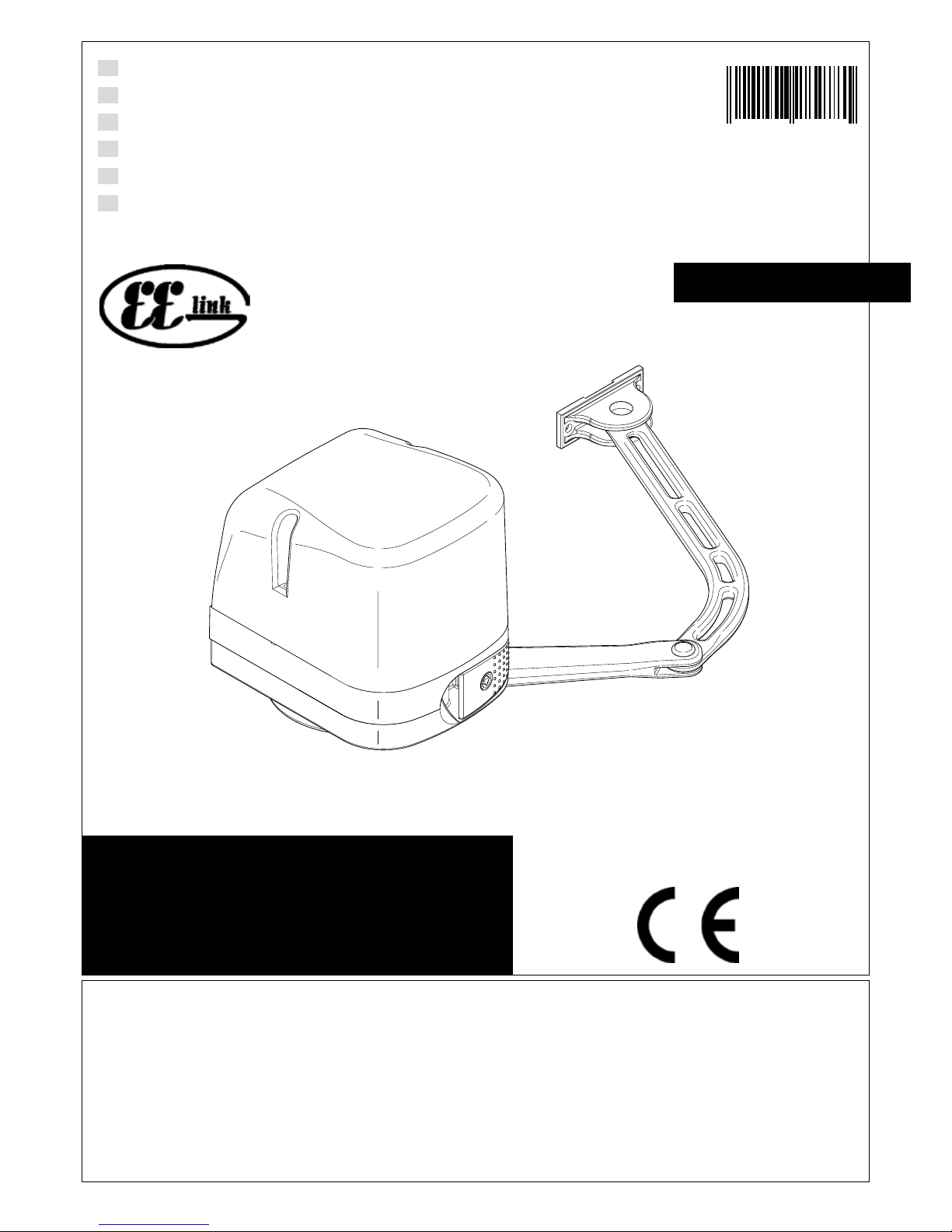
2) GENERAL OUTLINE
Low-voltage operator (24V ) suitable for residential use. Designed for
swinggateshavingsmall-sizedpillars.The operating arm,withitsspecial
antishearing shape, allows the leaves to be manoeuvred even when the
operator is positioned well away from their fulcrum. The irreversible
electromechanical gearmotor keeps the gate locked in the closing and
opening positions.
Thereleaselever,ttedtotheoutsideofeachoperator,allowsthemanual
manoeuvre to be carried out very easily.
ATTENTION! The VIRGO model controller is not equipped with mecha-
nical torque adjustment. It is compulsory to use a control panel of the
same manufacturer, in compliance with the basic safety requirements
of directives 2006/95/CEE, 2004/108/CEE, 2006/42/CEE equipped with
appropriate electric adjusment of the torque.
Before carrying out the manual manoeuvre make sure that this operation
will not create a dangerous situations.
Check in the relevant literature that the thermal eld in the working area
is suitable for the operator.
Make sure that the movement of the door does not cause entrapment
risks between the movable and xed parts of the door.
If swing gates with built-in doors are used, the motor must not run when
the door is left open.
WARNING! The operator must be installed by a qualied technician as
special safety components are used for every specic site and therefore
safety depends on installation.
3) TECHNICAL SPECIFICATIONS
3.1) VIRGO OPERATOR
Motor: ..........................................................................................24V 2500 min-1
Power: ..................................................................................................................110W
Insulation class:..........................................................................................................F
Lubrication:................................................................................Permanent grease
Reduction ratio:.............................................................................................. 1-1224
Output shaft revolutions: .................................................................2 min-1 MAX
Opening time 90°:................................................................................................ 14s
Torque supplied: ..........................................................................................170 Nm
Max leaf weight and length:....................2000N (~200kg) for 2m long leaf
Impact reaction: .........................................................Integrated torque limiter
.................................................................................................on LINX control panel
Motion drive:............................................................................................. Lever arm
Stop:................ Incorporated electrical limit switches + mechanical locks
Manual manoeuvre: ...............................................Release lever with CLS key
Number of manoeuvres in 24h: ........................................................................ 60
Environmental conditions:...................................................from -15 to +50 °C
Degree of protection:........................................................................................ IPX4
Operator weight: ......................VIRGO:80N (~8kg) - VIRGO SQ:60N (~6kg)
Dimensions:...................................................................................................see g.1
3.2) LINX CONTROL PANEL
Power supply: ....................................................................... 230V~ ±10% 50Hz*
Mains/low voltage insulation: ............................................> 2MOhm 500Vdc
Working temperature ............................................................from -15 to +50 °C
Dielectric strength: ....................................... mains/l.v. 3750V~ for 1 minute
Motor output current: .................................................................3.5A+3.5A max