Elastix ELX-3000 Manuale utente

Elastix Appliance
Assembly Process Guide
ELX-3000
PaloSanto Solutions
January, 2012
I. INDIVIDUAL PARTS
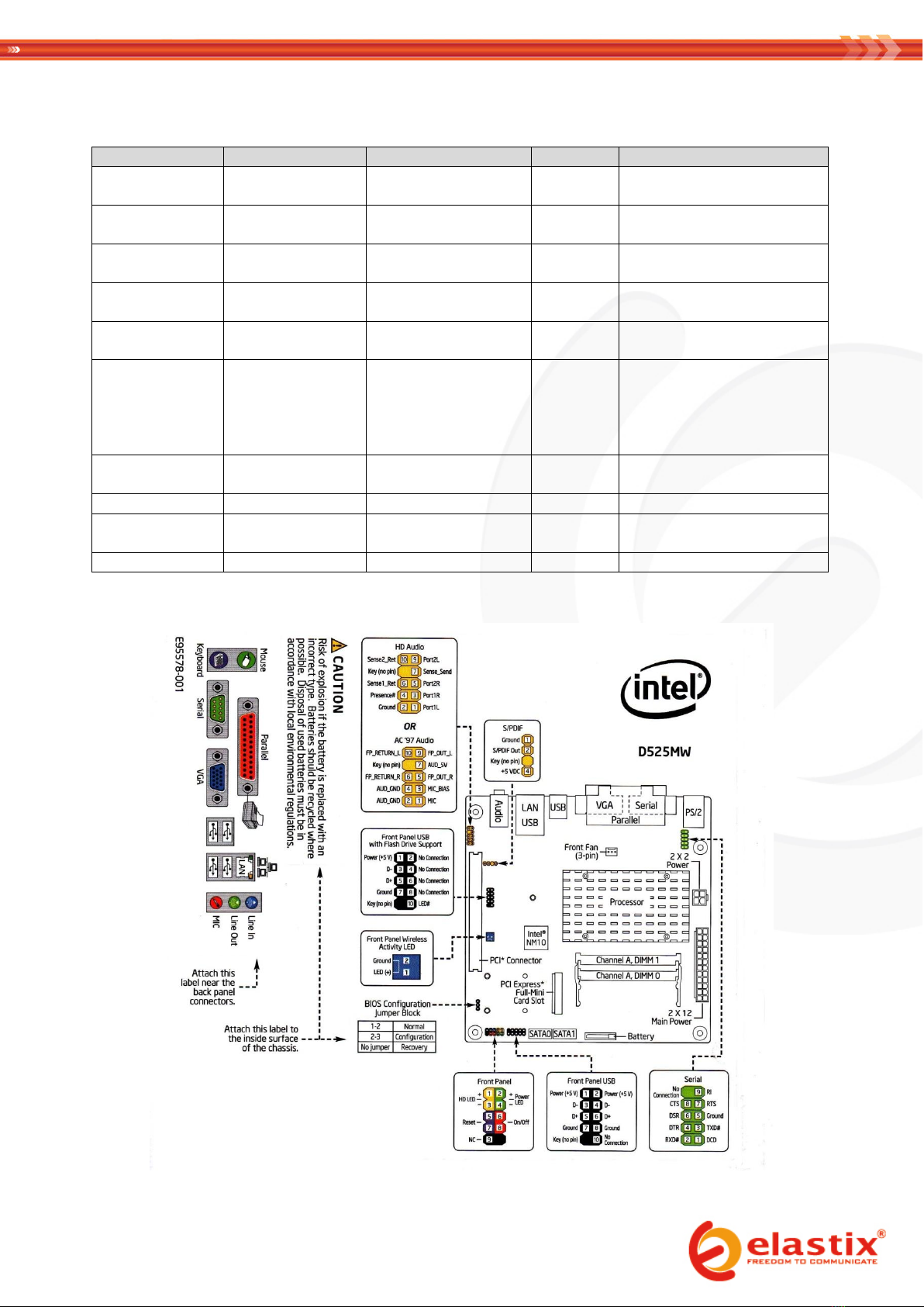
Hardware
Brand
Model
Type
Notes:
Mainboard
Intel
D525MW
Innovation
Series
Hardware included:
- SATA drive data cable
Processor
Intel
Dual Core Intel®
Atom™ processor D525
N/A
Intel® NM10 Express Chipset
Memory
Kingston / Corsair
DDR3 800/1066/1333
MHz
2 GB
Up to 4 GB
Hard Drive
Seagate / Samsung
/ Toshiba
Laptop Size SATA drive
500 GB
Power Cord Cable
N/A
110V or 220 V
N/A
Model depends on region it is
shipped to
1U customized
case w/
integrated 90W
Power Supply
Unit (PSU)
EMKO
ELX3000
N/A
Includes customized faceplate
for the Intel D525MW
motherboard
LCD
Crystalfontz
CFA635-TFE-KU1
LCD
USB LCD 20x4 +Keypad, White
Edge LED Backlight
LCD USB Cable
Crystalfontz
WRUSBY11
Cable
USB Cable for LCD Panel
Flexible PCI Riser
(dual)
idotPC
RS-1U2 B
N/A
N/A
Case Fan Cooling
Dynatron
DF124010BM
40mm Fan

II. ASSEMBLY
1. Match the faceplate on the back of the case to each port on the back of the motherboard
2. Remove the protective plastic sticker off the LCD screen
3. Screw the LCD screen to the case
4. Screw the motherboard to the bottom of the case
5. Insert the memory module in the motherboard’s memory slot
6. Connect the 24-pin ATX power connector coming from the PSU to the motherboard’s power connector (2 x 12)
7. Screw the fan to the left side of the case and connect its power cord to the PSU
8. Connect the POWER SWITCH cable (orange-white) to the motherboard
9. Connect the HDD LED and Power cables (green-white and red-white , respectively) to the motherboard
10. Screw the SATA disk to the bottom of the case
11. Connect the data cable of the SATA disk to the motherboard
12. Connect the power cable of the SATA disk to the PSU
13. Connect the provided USB cable (WRUSBY11) from the LCD panel (CFA635-TFE-KU1) to an internal USB port of
the motherboard
14. If necessary, insert the flexible riser into the PCI slot, after having set its jumper according to the following
diagram:
15. Secure cables conveniently using nylon cable ties
NOTE: the assembly process will be completed in the VII. PACKAGING section of this document, once the installation of
Elastix has been finished and tested
III. PRE-INSTALLATION
1. Connect the data and power cables of a SATA CD or DVD drive to the motherboard (skip this step if installing
Elastix from an external optical drive instead)
2. If instead an external optical drive is used for the installation (not recommended), connect it to the
corresponding port on the back of the ELX-3000
3. Connect the Power Cord Cable to the PSU connector on the back of the ELX-3000 and then to a nearby outlet
4. Press the power button to turn on the appliance
5. Place in the optical drive a CD or DVD containing the latest Elastix stable 32 bits version found in
http://sourceforge.net/projects/elastix/files/Elastix%20PBX%20Appliance%20Software/
(this guide was written using Elastix 2.2)
White
Orange
White
Green
White
Red
USB
Red
White
Green
Black

6. Reboot the appliance if necessary until the following screen is displayed:
IV. ELASTIX INSTALLATION
1. Press ENTER to begin the installation
2. Select English as the language for the installation:

3. Select 'us' as the type of keyboard:
4. Choose “Remove all partitions on selected drives and create default layout.”:

5. Confirm the removal of the partitions by selecting Yes:
6. Choose not to review or modify the partitioning layout:

7. Select to configure the Network Interface:
8. Select to activate on boot and to enable IPv4 support:

9. Manually assign the IP address 192.168.1.251 / 24:
10. Enter 192.168.1.1 as the Gateway and Primary DNS addresses:

11. Type 'elx.palosanto.com'as the hostname:
12. Select the time zone according to the city where the appliance is going to be used in:

13. Type 'palosanto'as the password for root:
14. Wait until the package installation finishes:
Altri manuali per ELX-3000
1
Indice
Altri manuali Elastix Sistema di conferenza

Manuali Sistema di conferenza popolari di altre marche

Kramer
Kramer VIA GO Manuale utente

AVT
AVT MAGIC AC1 Go Manuale utente

ProSoft Technology
ProSoft Technology AN-X4-AB-DHRIO Manuale utente

Sony
Sony PCS-I150 Manuale utente

Middle Atlantic Products
Middle Atlantic Products VTC Series Manuale utente

Prentke Romich Company
Prentke Romich Company Vanguard Plus Guida


