Page2 / 36 January 18, 2024, © Elcon, Switzerland EL-32_V3.0a_en.docx
Table of Contents:
1Introduction ..................................................................................................................................... 3
2Assembly of the display module ..................................................................................................... 3
2.1 Parts lists................................................................................................................................ 5
2.2 Step by Step assembly and testing of printed circuit boards................................................. 7
2.2.1 Assembling the PCB.......................................................................................................... 7
2.3 Plug assembly........................................................................................................................ 8
2.3.1 Initial test of the PCB ....................................................................................................... 10
2.4 Converting the FT-221 ......................................................................................................... 10
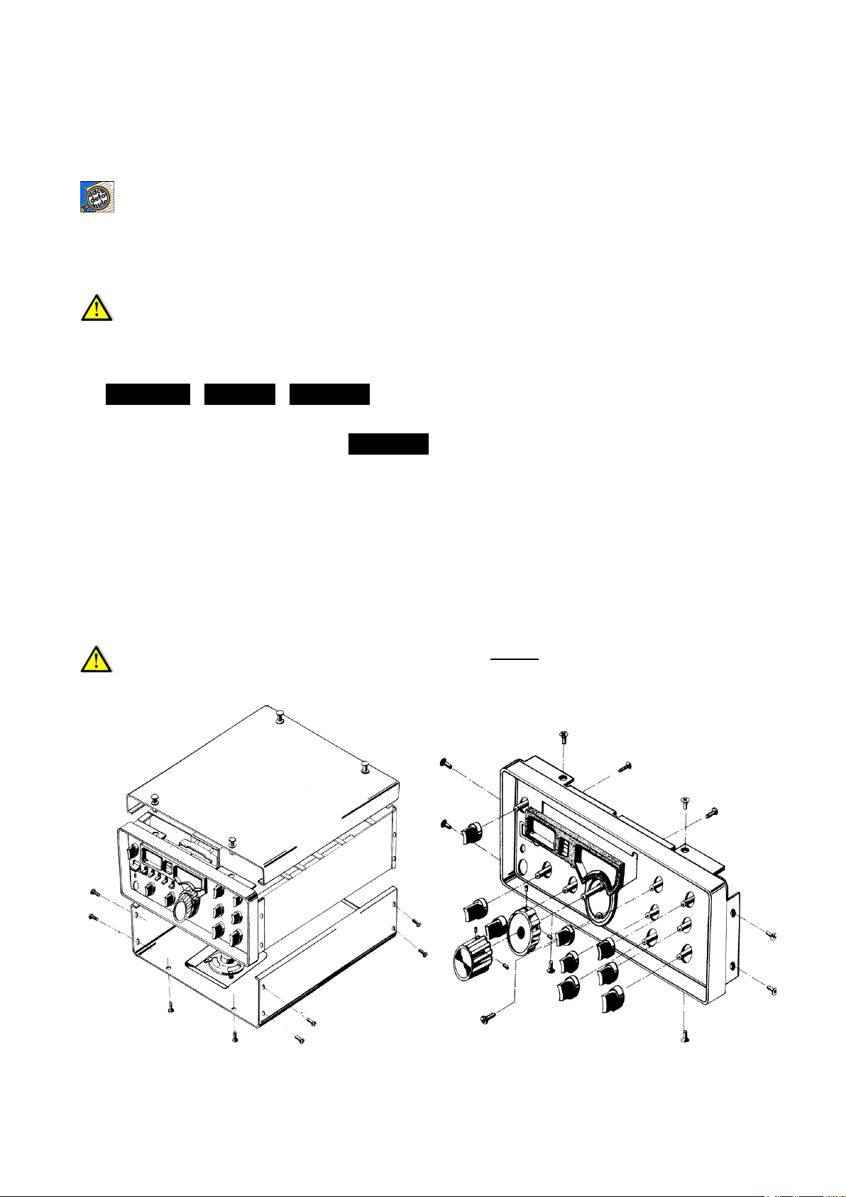
2.4.1 Removing the analog display from the FT-221................................................................ 10
2.4.2 Installation of the new digital display board in the FT-221............................................... 13
2.5 Start-up and adjustments..................................................................................................... 15
2.5.1 Adjusting the voltage measurement circuit...................................................................... 15
2.5.2 Adjustment of the frequency measuring circuit................................................................ 16
2.5.3 Test of the CTCSS encoder............................................................................................. 18
2.5.4 Adjustment of the CTCSS encoder.................................................................................. 18
2.5.5 Assembly.......................................................................................................................... 19
3Operation and functions................................................................................................................ 21
3.1 Display.................................................................................................................................. 21
3.2 Communication with the display module.............................................................................. 21
3.3 Menu structure ..................................................................................................................... 22
3.4 Operating modes.................................................................................................................. 23
3.4.1 Frequency Display ........................................................................................................... 23
3.4.2 Voltage Display................................................................................................................ 25
3.4.3 Morse readout of frequency............................................................................................. 25
3.4.4 Morse readout of voltage ................................................................................................. 25
3.4.5 Sound settings ................................................................................................................. 26
3.4.6 CTCSS (Continuous Tone Coded Squelch System)....................................................... 26
3.4.7 CTCSS memory for repeater operation........................................................................... 27
4Software Update ........................................................................................................................... 29
4.1.1 Installing the USB-updater software on the PC............................................................... 29
4.1.2 Installing the USB driver software.................................................................................... 29
4.1.3 Transferring the software updates in the EL-32............................................................... 31
5Appendix....................................................................................................................................... 32
5.1 Specifications ....................................................................................................................... 32
5.2 Rulers................................................................................................................................... 32
5.3 Repair / Warranty ................................................................................................................. 33
5.4 Disclaimer of liability............................................................................................................. 33
5.5 PCB assembly...................................................................................................................... 34
5.6 Schematic............................................................................................................................. 35
5.7 Notes.................................................................................................................................... 36
Important!
Advices or tips for the correct function of the EL-32.
Caution!
The instructions must be observed carefully.