Setting Service Telephone Numbers
Installation
Setting Service Telephone Numbers
The service telephone numbers can be saved in the Flash memory of the microcontroller of the voice module or
in the memory of the SIM card.
The numbers saved in the SIM card can be used only if there are no service numbers saved in the Flash
memory of the microcontroller.
Storage and deletion of service telephone numbers in the Flash of the microcontroller.
The record can be performed when SW1-3 is ON. The GREEN LED flashes during recording.
The recording is performed by sending SMS to the voice module in the following format: number of the service
telephone (1, 2, or 3), followed by a 10-digit number, for example, 1XXXXXXXXXX. When the service numbers
are saved, the voice module sends confirmation via SMS OK 1XXXXXXXXXX.
The deletion of the service numbers from the Flash of the microcontroller is performed after sending SMS
containing “9”. At the end of the record, SW 1-3 is set in position “OFF” and the device is restarted by
sequentially turning the power off and on.
Record of service telephone numbers in the SIM card.
The SIM card that will be used by the device is inserted in a mobile phone.
Up to 3 service numbers are entered in the contact list. The entered phone numbers can be saved in
+xxxxxxxxxxxx format, or in 0xxxxxxxxx format. The order of the entered service numbers is important. The
device makes an attempt to connect to the first entered number. In case of failure, it calls the second one, and
if it fails again, it calls the third one.
The SIM card is inserted when the device is powered off.
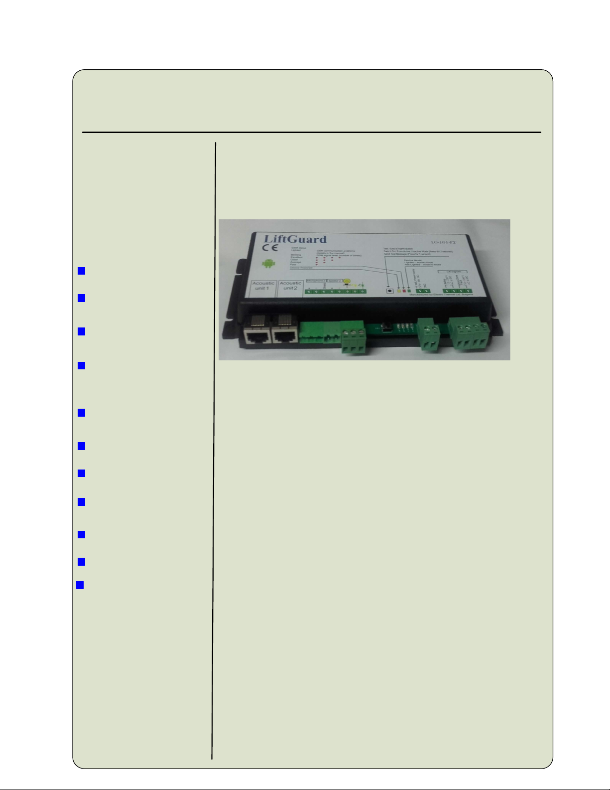
The power supply and signal cables have to be connected accordingto the scheme or to the label located on the top of the
communication unit.
Electrical Installation
2
Electrical installation has to be done by qualified personnel.
During the electrical installation the whole system has to be powered off.
In case of using acoustic unit, connected via the patch cable to the basic unit, the call button in the cabin has to be
connected to the two pins of the terminal block of the acoustic unit.
The used button has to be NO (normally open).
If instead of acoustic unit, separate microphone, loudspeaker, button, and LEDs are used to the second channel, the
polarity of the signal according to the label should be kept.
The call button has to be NO (normally open). One of its pin should be connected to terminal block on the
communication unit’s PCB according to the label. The second PIN is connected to – or + of the communication unit’s
Power supply.
The cathodes of the LEDs should be connected to the corresponding pins of the terminal block – yellow and green.
Their anodes should be connected to the plus of the power supply.
When the communication unit is powered on, the yellow LED is lighted.
Lift signals Safety Chain and Door Zone (Fault) can be in the
range 12 – 230 V AC or DC.
The current through the LEDs is about 8mA no matter the power supply voltage value 12 V or 24 V. The lift signals
Safety Chain and Door Zone (Fault) should be connected to the corresponding terminal blocks. In case of DC signals,
one PIN of the terminal block should be connected to the minus of the power supply and the second to the lift signal
as the polarity does not matter.
!
!
!
Operating modes and settings
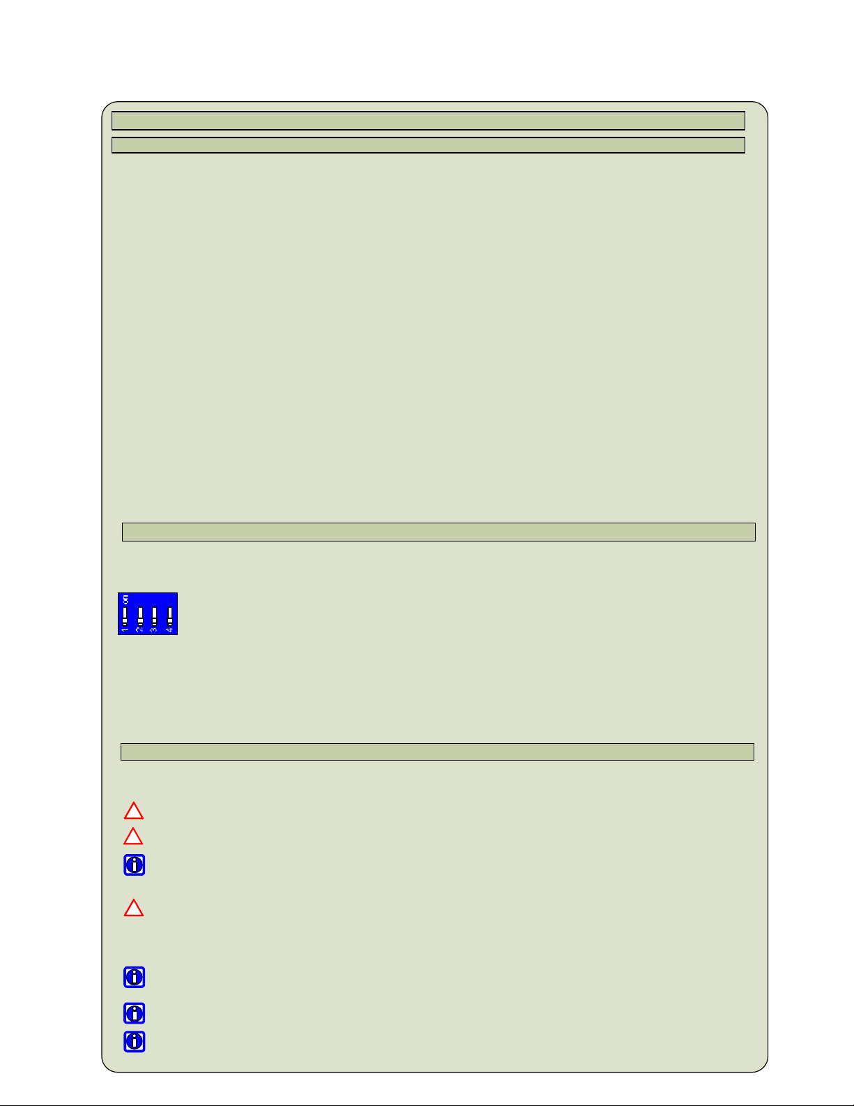
When Switch 1-1 is OFF and there is a call from a service phone, the call is performed via
acoustic unit 1. When Switch 1-1 is ON, the call is performed via acoustic unit 2.
When Switch 1-2 is OFF, the call on the second channel is always allowed, regardless the
status of the lift signals (filter).
When Switch 1-2 is ON, the filter is activated in the same way as with the first acoustic unit.
When Switch 1-3 is ON, the device is in the mode of recording service numbers in the
microcontroller.
When Switch 1-4 is OFF, the speaker’s voice level has normal values.
When Switch 1-4 is ON, the speaker’s voice level has higher values, suitable for big cabins.
SW 1