Elite Robo Slide Manuale utente

eliteaccess.com
®
ACCESS SYSTEMS INC
A C C E S S S Y S T E M S I N C
Instruction Manual
ROBO SLIDE
Residential Gate Operator
Installation instructions and manual book for
architects, general contractors and dealers
C
opyright © 2000 by Elite Access Systems, Inc. – www.eliteaccess.com
Click on the desired topic in the “Bookmarks” column or “Table of Contents” to select page.

TABLE OF CONTENTS
Important Notice
Safely Operating Gate
Configuration and Specifications
Warnings and Precautions
Step 1: Getting Started
Step 2: Mounting Operator
Step 3: Chain Installation
Step 4: Gate Movement Direction
Step 5: DC Power Supply Connection
Step 6: “Optional” Solar Panel
Step 7: Terminal Connections
Step 8: Adjusting Gate Travel Distance
Step 9: Timer
Step 10: 2-Way Adjustable Reversing Sensor
“Optional” Input Board
Master and Slave Operators with Timer
Master and Slave Operators without Timer
Control Board Functions
LED Descriptions
Troubleshooting
How to Reset Breaker Switch
How to Check Fuses
Gate will not close!
Gate will not open!
If you hear a “BEEP” sound
Robo Slide Parts List
Robo Slide Parts
2
3
4
5
5
6
6
7
8
9
10
11
11
12
13
14
15
16
17-18
19
19
20
20
21
21
22
PLEASE DO NOT TOUCH ME!...UNLESS YOU ARE AN AUTHORIZED SERVICE TECHNICIAN!
© COPYRIGHT 1992 BY ELITE ACCESS SYSTEMS, INC.
Release 6
All rights reserved. No part of this manual may be reproduced in any means; graphic,
electronic, mechanical, or photocopied without the express written permission of the
publisher of this material
1
5/01

IMPORTANT NOTICE
Closing
Closing
Incorrect Installation
using a Catch Post!
Correct Installation with Catch Rollers
Wall
Catch Rollers
Gate
1/2" Clearance
Between Gate
and Rollers
Minimum Clearance of 5" Between Back of Gate
and Wall or Other Objects in Gate's Path
1/4" Clearance from Top of Gate
5"
A physical stop MUST be installed on the gate prior to installation of the gate
operator. This will assure that the gate does not derail while in motion.
CAUTION
Gate in Fully Opened Position Gate Clearances
IMPORTANT!
Because gate coasting distance varies with temperature, Elite DOES NOT
recommend the installation of a catch post. This could cause the gate to collide with the post.
Guide Rollers
(Elite Part # A UHM)

SAFELY OPERATING GATE
Owners Must Never Let Pedestrians Cross the Path of a Moving Gate!
Owners Must Never Mount Any Gate Operating Devices Accessible In Between the Gate and the Wall!
Owners Must Never Mount Any Gate Operating Devices Accessible Through the Gate!
CAUTION
CAUTION
CAUTION

CONFIGURATION AND SPECIFICATIONS
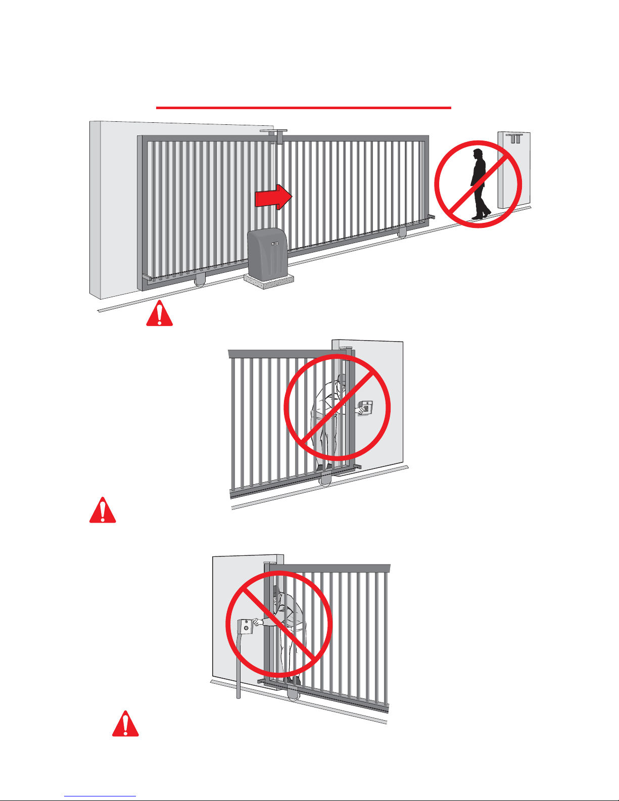
Elite's Recommended Gate Setup Configuration
Warning Signs on Both Sides of Gate
Over-Travel Stops
on Both Ends of
Gate Rail
Guide Rollers Guide Rollers
2"x 2" Mesh Wire
Across Entire Gate
Warning Sign Clearly Visible on Gate Operator
Be sure to read and follow all Elite's instructions before installing and operating any
Elite product. Always disconnect the gate operator's power source before repairs are
attempted. Elite Access Systems, Inc. is not responsible for improper installation or
failure to comply with local building codes.
CAUTION
Robo Slide Specifications:
Gate Speed – 11 inch per second
Maximum Gate Length – 20 feet
Maximum Gate Weight – 800 pounds
Maximum Cycles – 70 cycles per day with Elite's Plug-In Transformer.
–Solar power cycles per day varies, Contact Elite for more Information
–Battery back-up cycles (50 cycles total)
AC Power Supply – 18 VAC 2.0 Amp Plug-In Transformer (Elite Part # A POW-1)
AC Power Supply Wire – 14 gauge or greater landscape lighting cable rated for direct burial and
300 watts at maximum length of 1000 ft
DC Power Supply – Built-in, back-up for AC or Solar power failure only
Solar Power – Optional (Elite Part # SOLAR 3)
Reinforced Concrete to Bolt Operator on
18 VAC Plug-In Transformer,
for Each Gate Operator U.L. Listed Underground Conduit for Wires
3" Maximum Picket Width
Steel V-Groove, High Speed Ball Bearing Wheels

READ ENTIRE OWNERS MANUAL BEFORE INSTALLATION
CAUTION
Model:
Warnings and Precautions
DO NOTUse for Apartment or Condominium Applications.
1. Do not tighten chain too tight
2. Use proper type of wheels - only 4" steel wheels with high speed ball bearings
3. Do not use a 12V transformer - use only 18 VAC 2.0 Amp
4. Do not install as a rear-mount installation
5. Use only 14 gauge or greater landscape lighting cable rated for direct burial and 300 watts
Robo Slide For Single Home Applications.
STEP 1: Getting Started
This gate operator is designed for single home application, or for limited commercial
applications. An example of a commercial application would be a factory facility with
limited cycles per day, using a plug in transformer or solar panel.
PLEASE DO NOT REPAIR ME!...UNLESS YOU ARE AN AUTHORIZED SERVICE TECHNICIAN!

Correct Chain Installation Incorrect Chain Installation
Too High
Too Low
STEP BY STEP INSTALLATION
STEP 2: Mounting Operator
STEP 3: Chain Installation
Pour concrete bed for Robo Slide. Minimum size of bed is 20" x 15" x 20"d. Suggested
installation for bolts is 1/2" x 3 1/2" (for red-head fastener).
Minimum space between gate and output sprocket must be 4". After you position the gate
operator, bolt-down the operator to the concrete bed. Make certain that the concrete bed is solid.
6"
Concrete
(Reinforced Recommended)
Above
Ground
Power Supply Line
20"
20"
15"
10"
8"
OVERLOAD
POWER
CHARGEOK
BATTERYLOW
OPENRELAY
CLOSERELAY
TIMERUP
ON
W1
OFF
OPENTORIGHT
600
PW
CENTRALCONTROL
SYSTEMON
DCOPERATORv5M
MADEINUSA
ALARM
SENSORREVERSE
SENSOR
HEAVY
GATE
FIRE
DEPT
STRIKE
OPEN
SAFETY
LOOP
EXIT
LOOP
RADIO
REC
CHARGING
POWERBOARD
POWER
CHECK
FUSE
J2
Red Head Fastener
1/2" x 3 1/2"
Gate
Incorrect Chain Spacing
4" MinimumGate
Correct Chain Spacing
or
Gate Front
Gate Rear

STEP BY STEP INSTALLATION
STEP 4: Gate Movement Direction
Plug in the limit/motor harness wires to the left socket (#1) if your gate, from the inside of
the property, opens to the left and closes to the right. Plug into the right socket (#2) if the
gate opens to the right and closes to the left from the inside of the property.
OVERLOAD
POWER
CHARGE OK
BATTERY LOW
OPEN RELAY
CLOSE RELAY
TIMER
UP
ON
W1
OFF
OPENTORIGHT
Socket #1
Socket #2
60 0
PW
CENTRAL CONTROL
SYSTEMON
DCOPERATORv 5M
MADE IN USA
ALARM
SENSOR
REVERSE
SENSOR
HEAVY
GATE
FIRE
DEPT
STRIKE
OPEN
SAFETY
LOOP
EXIT
LOOP
RADIO
REC
CHARGING
POWER BOARD
POWER
CHECK
FUSE
J2
OUT
IN
OUT
IN
Open to Right
Open to Left
Socket #1
Socket #2

OVERLOAD
POWER
BATTERY LOW
OPEN RELAY
CLOSE RELAY
TIMER
UP
ON
OFF
60 0
PW
CENTRAL CONTROL
SYSTEMON
DCOPERATORv 5M
MADE IN USA
ALARM
SENSOR
REVERSE
SENSOR
HEAVY
GATE
FIRE
DEPT
STRIKE
OPEN
SAFETY
LOOP
EXIT
LOOP
RADIO
REC
CHARGING
POWER BOARD
POWER
CHECK
FUSE
J2
CHARGE OK
CHARGE OK
OVERLOAD
POWER
BATTERY LOW
OPEN RELAY
CLOSE RELAY
TIMER
UP
ON
W1
OFF
OPENTORIGHT
60 0
PW
CENTRAL CONTROL
SYSTEMON
DCOPERATORv 5M
MADE IN USA
ALARM
SENSOR
REVERSE
SENSOR
HEAVY
GATE
FIRE
DEPT
STRIKE
OPEN
SAFETY
LOOP
EXIT
LOOP
RADIO
REC
CHARGING
POWER BOARD
POWER
CHECK
FUSE
J2
CHARGE OK
STEP BY STEP INSTALLATION
Use Elite's optional 18 VAC plug-in transformer (Elite Part # A POW-1). Hook up the
transformer to 115 VAC. Use two, low voltage, 14 gauge / 300watt direct burial, landscape
lighting cables. Hook these wires to the two yellow wires from the control board to the
plug-in transformer.
STEP 5: DC Power Supply Connection
18 VAC Plug-in Transformer
14 Gauge Wires Maximum Wire Length
should not exceed 1000 ft.
Polarity Does Not Matter
2
1
3
5
6
8
10
7
9
4
Yellow Wires #2, #4
Do Not use solar panel and plug-in
transformer at the same time.
To
115 VAC
CAUTION
Beep!
After the plug-in transformer has been connected to the power source, connect the battery
cable plug to the limit/motor harness plug. You will immediately hear a beep for a few
seconds. After the beep, check the “Charge OK” LED......
Limit/Motor Harness
......it must be “ON”.

If you use Elite's optional solar panel (Elite Part # Solar 3). Connect the two wires from the
solar panel to the two yellow wires on the control board. Sunlight will energize the batteries
through the solar panel. This solar panel will charge up to 2800 Mamp/Hr in optimum
conditions & 500 Mamp/Hr in light overcast conditions. For detailed specifications consult
the Solar 3 Installation sheet.
OVERLOAD
POWER
BATTERY LOW
OPEN RELAY
CLOSE RELAY
TIMER
UP
ON
W1
OFF
OPENTORIGHT
60 0
PW
CENTRAL CONTROL
SYSTEMON
DCOPERATORv 5M
MADE IN USA
ALARM
SENSOR
REVERSE
SENSOR
HEAVY
GATE
FIRE
DEPT
STRIKE
OPEN
SAFETY
LOOP
EXIT
LOOP
RADIO
REC
CHARGING
POWER BOARD
POWER
CHECK
FUSE
J2
CHARGE OK
STEP BY STEP INSTALLATION
STEP 6: Optional Solar Panel Connection
Energizing Robo Slide with solar power only needs the radio receiver to operate the gate.
The only recommended external devices other than radio receivers are dry-contact
command devices which do not consume any current like key switches. Using other
devices that consume high current such as telephone access, magnetic locks or loop
detectors will cause excess drainage of the battery and eventually completely drain the
battery .
Elite recommends using 1 or
2 larger batteries (12 VDC, 30
Amp) (Elite Part # A 12330 or
A 12330 PACK) in Robo Slide
when using the optional solar
panel.
Polarity Does
Not Matter
2
1
3
5
6
8
10
7
9
4
Yellow Wires #2, #4
Do Not use solar panel and plug-in
transformer at the same time.
CAUTION
CAUTION
Solar Panel
(Elite Part # SOLAR 3)
No Stand
30 Amp.
12 VDC
For More Details,
contact your Local Dealer
Indice
Altri manuali Elite Apricancello


