elsner elektronik KNX PS640+ Guida

KNX PS640+ and
KNX PS640+USB
Power Supply Systems
EN
Installation and Adjustment
KNX PS640+
Item number 70141
KNX PS640+USB
Item number 70144


1 Content
Elsner Elektronik GmbH • Sohlengrund 16 • 75395 Ostelsheim • Germany
Power Supply Systems KNX PS640+ and KNX PS640+USB • from software version 1.01, ETS programme version 1.1
Status: 19.08.2020 • Technical changes and errors excepted.
1. Description ........................................................................................... 3
1.1. Deliverables .............................................................................................................. 3
1.2. Technical specifications ........................................................................................... 3
2. Installation and Commissioning ........................................................... 4
2.1. Installation notes ...................................................................................................... 4
2.2. Installation ................................................................................................................ 5
2.2.1. Housing .......................................................................................................... 5
2.2.2. Scheme .......................................................................................................... 6
2.2.3. Connection examples for a KNX system .................................................... 6
2.3. Power Supply ........................................................................................................... 7
2.3.1. Housing example with central operating unit ............................................ 7
2.4. Starting Position ....................................................................................................... 8
2.5. Key functions in display menu ................................................................................ 8
2.6. Line reset ................................................................................................................... 8
2.7. Data memory ............................................................................................................ 9
2.7.1. Operating hours ............................................................................................ 9
2.7.2. Overload ........................................................................................................ 9
2.7.3. External Overvoltage .................................................................................. 10
2.7.4. Internal Overvoltage ................................................................................... 10
2.7.5. Short Circuit ................................................................................................ 10
2.7.6. Excess Temperature ................................................................................... 10
2.8. Operating data ........................................................................................................ 10
2.9. Language ................................................................................................................ 11
3. Disposal ............................................................................................. 11
4. Transmission protocol ....................................................................... 12
4.0.1. Abbreviations .............................................................................................. 12
4.0.2. Listing of all communication objects ........................................................ 12
4.1. Setting of parameters (Software ETS) .................................................................. 13
4.1.1. General settings .......................................................................................... 13
4.1.2. Messages ..................................................................................................... 14
4.1.3. Current threshold value .............................................................................. 16

2 Clarification of signs
This manual is amended periodically and will be brought into line with new software
releases. The change status (software version and date) can be found in the contents footer.
If you have a device with a later software version, please check
www.elsner-elektronik.de in the menu area "Service" to find out whether a more up-to-
date version of the manual is available.
Clarification of signs used in this manual
Installation, inspection, commissioning and troubleshooting of the device
must only be carried out by a competent electrician.
Safety advice.
Safety advice for working on electrical connections, components,
etc.
DANGER! ... indicates an immediately hazardous situation which will lead to
death or severe injuries if it is not avoided.
WARNING! ... indicates a potentially hazardous situation which may lead to
death or severe injuries if it is not avoided.
CAUTION! ... indicates a potentially hazardous situation which may lead to
trivial or minor injuries if it is not avoided.
ATTENTION! ... indicates a situation which may lead to damage to property if it is
not avoided.
ETS In the ETS tables, the parameter default settings are marked by
underlining.

3 Description
Power Supply Systems KNX PS640+ and KNX PS640+USB
Version: 19.08.2020 • Technical changes and errors excepted.
1. Description
The Power Supply Systems KNX PS640+ and KNX PS640+USB deliver a 29 V
bus voltage for the KNX system and 24 V DC supply voltage for 24 V devices. Special
operating conditions such as short circuit, electrical surge, overcharge or excess tem-
perature are recorded and may be read off on the display. The present power discharge
is displayed as well. It is possible to reset the connected bus devices directly by means
of the key pad.
In addition all functions can be realised via the bus, too, e. g. the transfer of malfunction
messages and operating data and a time/period reset. Malfunction messages are
stored by the KNX PS640+(USB).
Functions:
• Delivers a 29 V KNX bus voltage (reduced), output current max. 640 mA,
short-circuit proof
• Delivers 24 V DC (not reduced), output current max. 150 mA
•Reset of a line directly on the device
• Record of operating hours, overload, external overvoltage, internal
overvoltage, short circuit and excess temperature
• Display of operating data bus voltage, bus current and temperature of the
device
• The display may be shown in German, English, Spanish or Dutch
•Bus connection for data transfer (e. g. malfunction messages, operating data)
• Possibility for reset and diagnostics via the bus
• Only KNX PS640+USB: USB interface for bus access via PC
Configuration is made using the KNX software ETS. The product file can be down-
loaded from the Elsner Elektronik website on www.elsner-elektronik.de in the “Ser-
vice” menu.
1.1. Deliverables
• Power Supply System
1.2. Technical specifications
Housing Plastic material
Colour White
Installation Snap-on fitting on mounting rails
Degree of protection IP 20
Dimensions approx. 123 x 89 x 61 (W x H x D, mm), 7 width units
Weight approx. 370 g
Ambient temperature Operating 0…+45°C, Storage -25…+70°C
Ambient air humidity 5...95% rH, avoid condensation
Operating voltage 230 V AC, 50 Hz

4 Installation and Commissioning
Power Supply Systems KNX PS640+ and KNX PS640+USB
Version: 19.08.2020 • Technical changes and errors excepted.
The product conforms with the provisions of EU directives.
2. Installation and Commissioning
2.1. Installation notes
Installation, testing, operational start-up and troubleshooting should
only be performed by an electrician.
CAUTION!
Live voltage!
There are unprotected live components inside the device.
• National legal regulations are to be followed.
• Ensure that all lines to be assembled are free of voltage and take
precautions against accidental switching on.
• Do not use the device if it is damaged.
• Take the device or system out of service and secure it against
unintentional use, if it can be assumed, that risk-free operation is
no longer guaranteed.
The device is only to be used for the intended purpose described in this manual. Any
improper modification or failure to follow the operating instructions voids any and all
warranty and guarantee claims.
After unpacking the device, check it immediately for possible mechanical damage. If it
has been damaged in transport, inform the supplier immediately.
The device may only be used as a fixed-site installation; that means only when assem-
bled and after conclusion of all installation and operational start-up tasks and only in
the surroundings designated for it.
Elsner Elektronik is not liable for any changes in norms and standards which may occur
after publication of these operating instructions.
Power consumption
Standby
approx. 2.3 W
Outputs • KNX bus voltage 29 V (reduced),
Output current max. 640 mA, short-circuit proof
• 24 V DC (not reduced), Output current max. 150 mA
• KNX data
Data output KNX +/- bus terminal plug
Group addresses max. 200
Allocations max. 200
Communication objects 27

5 Installation and Commissioning
Power Supply Systems KNX PS640+ and KNX PS640+USB
Version: 19.08.2020 • Technical changes and errors excepted.
2.2. Installation
Observe the correct installation. Incorrect installation may destroy the power supply
system or connected electronic devices.
After the auxiliary voltage is applied the device will enter an initialisation phase lasting
5 seconds. During this phase no information can be received via the bus.
2.2.1. Housing
2Fig. 1
1 Bus voltage power
OUT (KNX terminal + / -)
2 Programming LED and
programming bushbutton
3 Bus data (KNX terminal
+ / -), connection for line
or main line or sector
4 Input operating voltage
230 V AC, L / N / PE
5 USB interface
(only KNX PS640+USB)
6 Output direct current voltage
24 V DC, + / -
Connections 4 and 6 are suitable for
solid conductors up to 1.5 mm² or con-
ductors with fine wires.
4
13
5 6

6 Installation and Commissioning
Power Supply Systems KNX PS640+ and KNX PS640+USB
Version: 19.08.2020 • Technical changes and errors excepted.
2.2.2. Scheme
2.2.3. Connection examples for a KNX system
Auxiliary supply 24 V DC
(max. 150 mA)
Fig. 2
0...+45°C
Fig. 3a
without line coupler
Fig. 3b
with line coupler

7 Installation and Commissioning
Power Supply Systems KNX PS640+ and KNX PS640+USB
Version: 19.08.2020 • Technical changes and errors excepted.
2.3. Power Supply
2.3.1. Housing example with central operating unit
Fig. 4
8 Installation and Commissioning
Power Supply Systems KNX PS640+ and KNX PS640+USB
Version: 19.08.2020 • Technical changes and errors excepted.
3. Settings of the device
3.1. Starting Position
The following may be read off and set on the display of the power supply system KNX
PS640+:
• Reset of a line
• Recall of the data memory with operating hours, overcharge, external electrical
surge, internal electrical surge, short circuit and excess temperature
• Recall of the operating data bus voltage, bus current and temperature
• Language of display
The display is dimmed after 60 seconds if during this period no key is pressed.
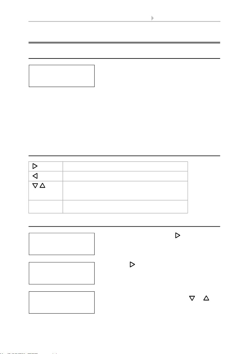
3.2. Key functions in display menu
3.3. Line reset
Confirms the selection, moves to the next step.
One step back.
Changes a setting (selects a setting or changes a
value). The cursor (the blinking rectangle) indicates
the selected menu item.
ok Confirms the settings and returns to the device main
menu.
elsner elektronik
KNX Power Supply
Normal Operation
Diagnostics >
elsner elektronik
KNX Power Supply
Normal Operation
Diagnostics >
In starting position, press key once.
Line Reset > ™
Data Memory >
Operating Data >
Language >
Press key once more in order to get into the sec-
tor „Line reset“.
Reset: Yes ™
No
30 seconds
Reset not active!
Move the cursor (flashing rectangle at right edge)
to the desired setting with the keys or and
confirm with key ok.
Altri manuali per KNX PS640+
2
Questo manuale è adatto per i seguenti modelli
3
Indice
Altri manuali elsner elektronik Alimentazione elettrica

elsner elektronik
elsner elektronik KNX PS640 Manuale di istruzioni

elsner elektronik
elsner elektronik KNX PS640+ Guida

elsner elektronik
elsner elektronik KNX PS640 4U Manuale utente

elsner elektronik
elsner elektronik KNX PS640-IP 2U Guida

elsner elektronik
elsner elektronik KNX PS640-IP 2U Manuale utente

elsner elektronik
elsner elektronik KNX PS640+ Manuale utente

elsner elektronik
elsner elektronik KNX PS640 Manuale utente

elsner elektronik
elsner elektronik KNX PS640-IP 2U Manuale utente


