Embedded Micro Technology MyPi Manuale utente

Page 1
MyPi Industrial CM3+ Integrator Board
User Guide
Issue : 1.00
Dated : January 2022
Prepared By : Andrew O’Connell

Page 2
FEATURES
•Raspberry Pi Compute Module 1 & 3/3+ compatible
•Integrated 10/100 Ethernet adapter
•2 x USB 2.0 master interfaces
•Mini PCI-e Interface + SIM connector For use with cellular modems
•Ruggedised high speed USB interfaced µSD Card interface, providing additional storage
separate from the Compute Module eMMC flash
•Integrated USB RS232 UART (RX/TX/RTS/CTS) using RJ45 connector for maximum range.
•Modular IO Cards for application specific IO solutions
•Dual high-resolution Raspberry Pi camera interfaces
•Raspberry Pi 2 HAT compatible I/O connector & mounting points
•Integrated battery backed real-time-clock (RTC)
•Additional 1.6s hardware watchdog for added system resilience
•HDMI out
•2 x Bi-colour (red/green) front panel status LEDs
•8Way 2-part 3.5mm Screw terminal connector for use with modular IO card outputs or HAT
board
•Wide 7-24V (poly-fused and filtered) DC power input range
•Available in standard (0 to 70°C) and extended range (-25 to 80°C) temperature versions for
demanding environments
•Core PCB Size : 125 x 142mm

Page 3
BOARD IO FEATURES
❶
❷
❸
❹
❺
❻
❼
❽
❷
❿
⓫
⓬
⓭
⓮
⓯
⓰
⓱
⓲
⓳
❶Compute Module 1/3/3+ Socket
❷mPCIe Socket + Modem SIM Socket
❸USB µSD Card Interface + Socket
❹USB LAN9512 10/100 LAN + USB Interface
❺2 x USB 2.0 Ports
❻RJ45 RS232 Port (USB Interface)
❼I2C DS1339U-33+ RTC + Battery Backup
❽External Watchdog
❾Dual Bi-colour LED
❿GPIO IO Card interface + Front Connector
⓫Power In (9-24V DC)
⓬Raspberry Pi HAT Connector
⓭HDMI Out
⓮Dual Camera Interface
⓯Audio Out
⓰USB Hub
⓱Programming Mode Selector Link
⓲Watchdog Selector Links
⓳µUSB CM Programming port
⓴Modem Reset GPIO23 Link
❾
❹
❹
❹
❸
❿
❿⓫
⓴

Page 4
HARDWARE CONFIGURATION LINKS
LED - ACT
This LED indicates ‘Activity’ functionality on the Pi unit, by default this indicates eMMC flash access
on the module, but can be reassigned to indicate other status signals.
LK1 - WATCHDOG OUT
Fitted Connect External Watchdog Out Line to RPI RUN/RESET Line
Open Default
LK5 - WATCHDOG ENABLE
Fitted Connect External Watchdog Input Line to GPIO29*
Open Default
LK3 - WATCHDOG INPUT
Fitted Connect External Watchdog Enable to GPIO28*
Open Default
*GPIO LINES ALSO USED FOR CAMERA 0

Page 5
LK12 - mPCIe EMERGENCY RESET
Fitted Fit to connect GPIO23 to PERST (pin 22) of mPCIe socket
Open Default
LK6 - Compute Module Programming Mode (USB SLAVE BOOT MODE)
Fitted DIS Compute module programming forced as disabled
Fitted EN Compute module programming enabled (fit USB programming cable in to activate)

Page 6
LK9 - RS232 Connector 5V power Out
Fitted DIS DTR Line Floating
Fitted EN Fit to pull DTR RS232 line to +5V (default fitted)
LK8 - Green Status LED 1 Drive Source
Fitted 1-2 GPIO36 (default)
Fitted 2-3 mPCIe MODEM/WIFI Status LED Signal

Page 7
RASPBERRY PI COMPUTE MODULE PROGRAMMING
The unit as shipped is configured to allow the eMMC flash on the compute module to be re-
programmed
Demo kit units come complete with Compute modules that are pre-programmed with the demo
Raspbian OS pre-installed, this section describes how to write a new disk image to the Compute
Module.
First of all download the windows USB boot installer, this will install the device drivers as well as a
program we'll use later called RPi-Boot
Raspberry Pi RPI-BOOT Software Download Link
Connect the mini USB connector to the Windows PC using the supplied USB A to micro USB B data
cable, fit the programming mode jumper link (LK6) to EN and then power up the unit.
Windows will then show the following stages as it configures the OS :
Once that sequence has finished Windows has now installed the required drivers and you can power
off the unit for a moment whilst we get the PC side ready for the next step.

Page 8
Making sure you have the unit powered off start up RPi Boot, this is easiest done via the start menu,
we have found this needs to be run as ‘Administrator’ privilege mode for correct operation
When the RPi-Boot starts up it’ll sit and wait for the attached board to boot up :
Power up the unit and RPi-Boot will configure the unit to appear as a flash drive :
When done the compute module will alternate into mass storage mode (so behaving just as though
it's a USB memory stick) and windows will then recognise the module as an external drive.

Page 9
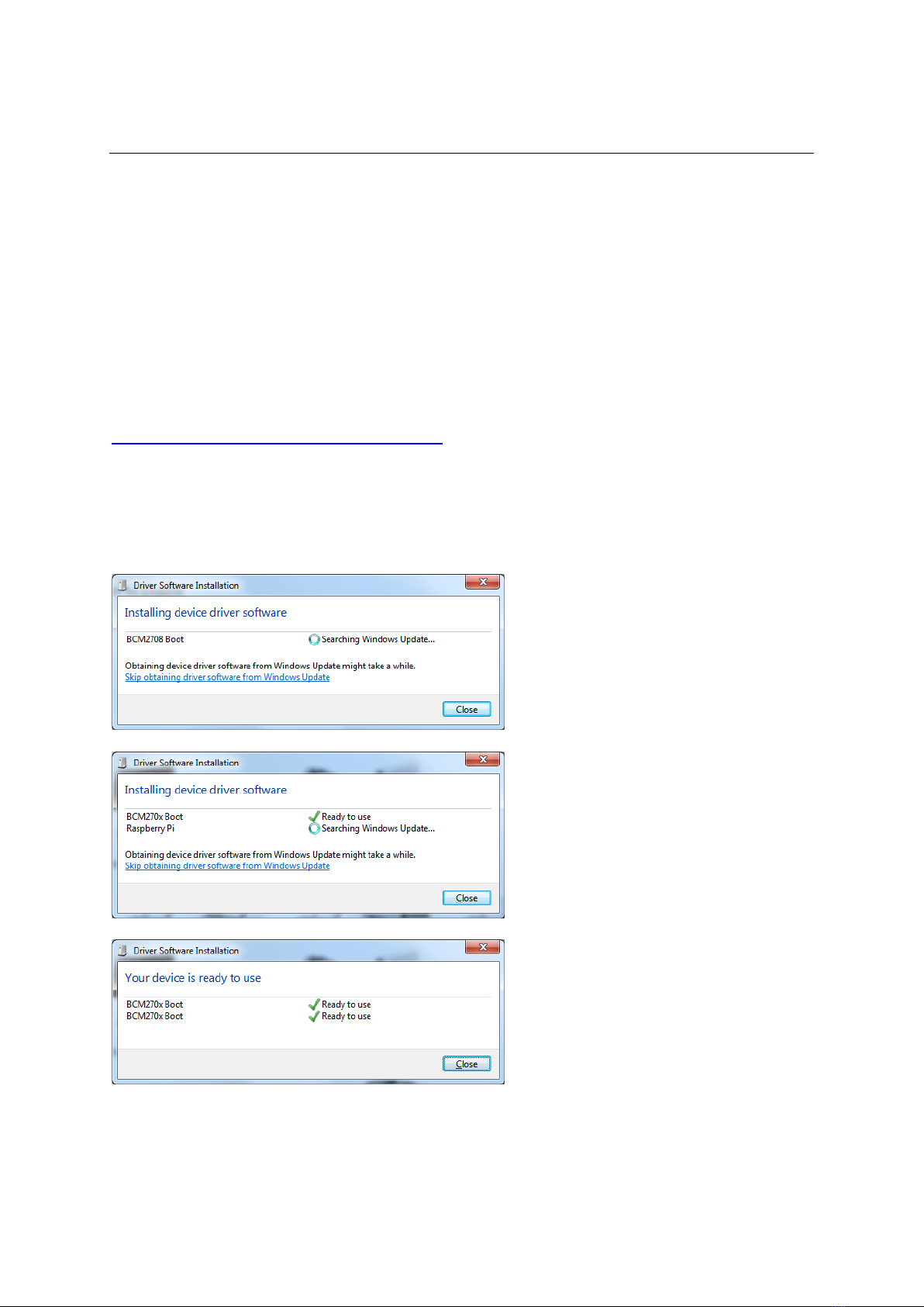
If the compute module eMMC already contains an OS Windows will recognise the FAT partition and
assign that (at least) a drive letter, this is useful in the event that a configuration error with the boot
files is made (e.g. dt-blob.bin or config.txt) and needs recovery actions to be performed.
After drive letter assignment Windows may indicate that partitions need scanning or fixing, these
can be ignored/cancelled.
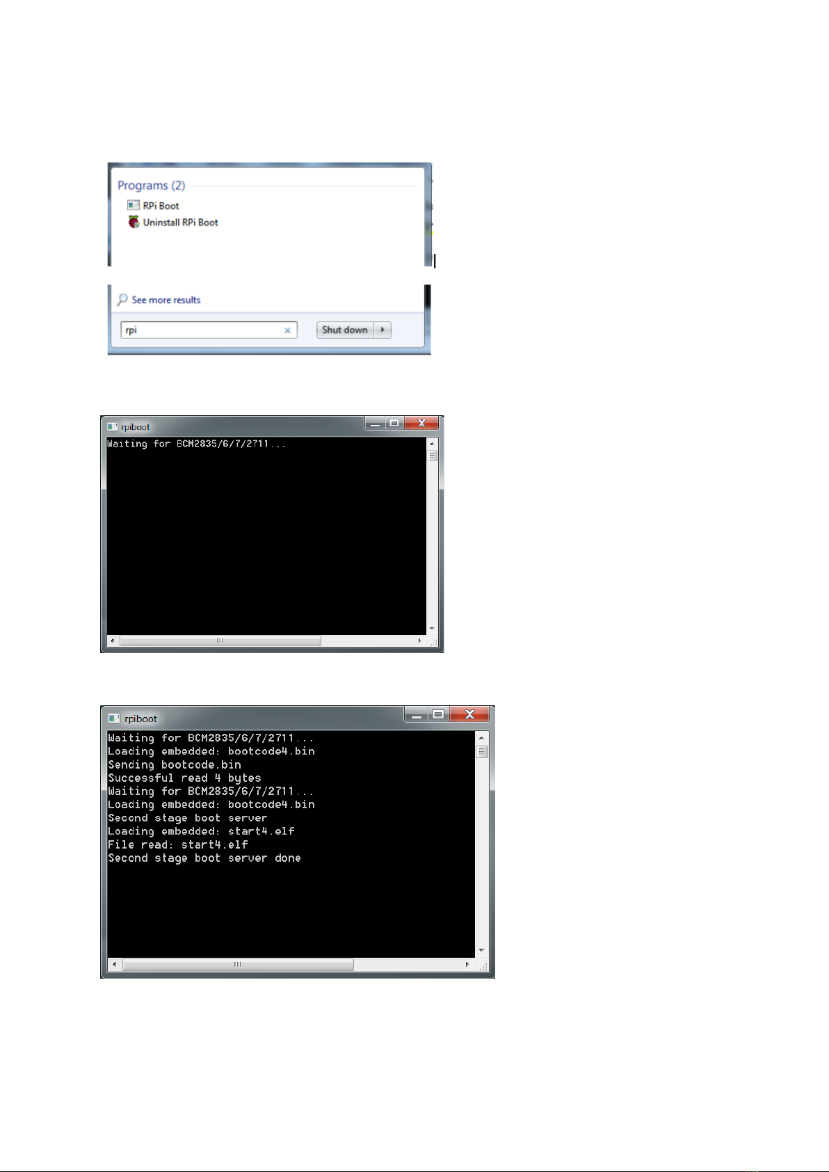
There are a few different ways we can load on the OS, for simplicity we’ll cover using the
recommended OS writing software and process from the main Raspberry Pi website
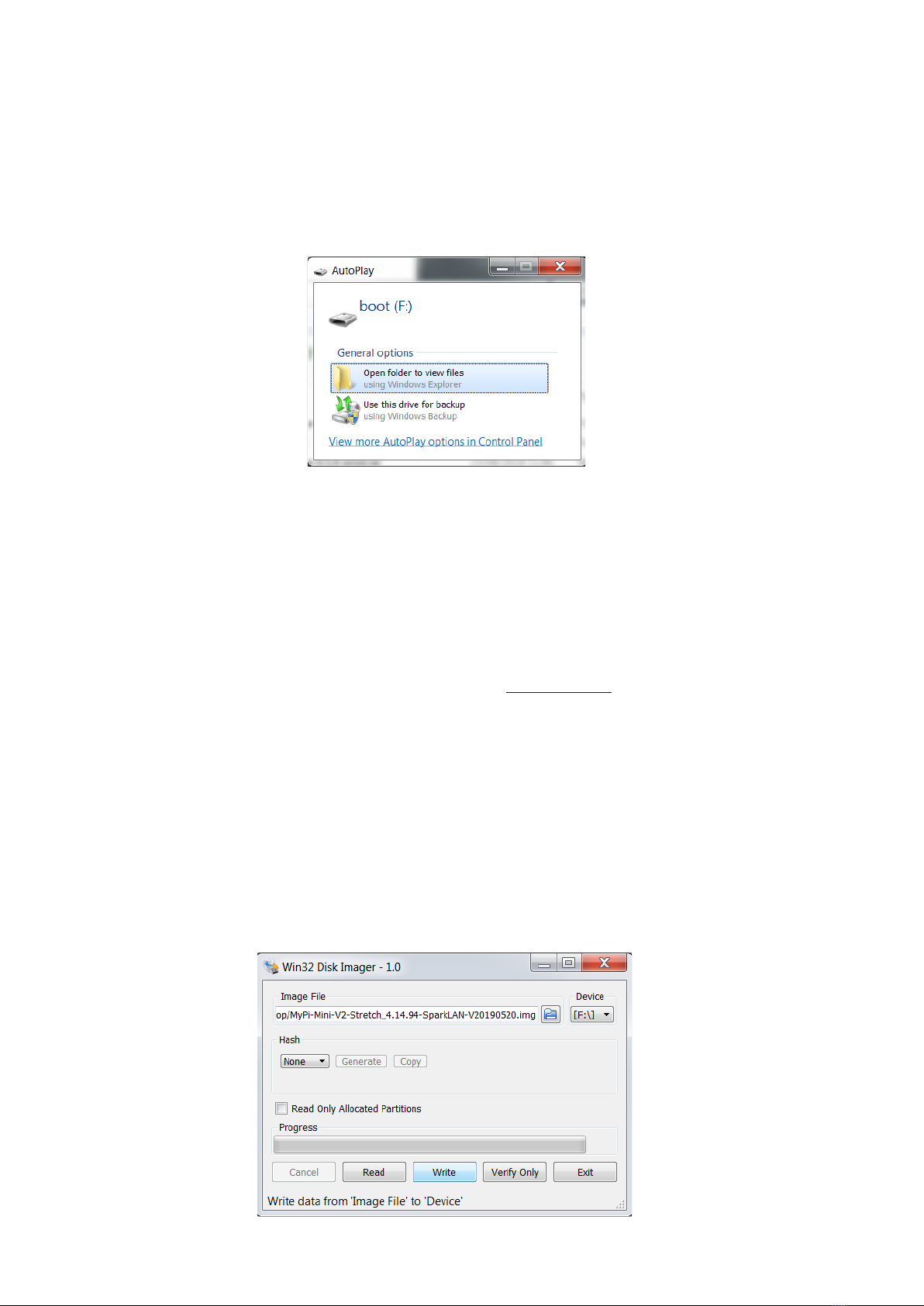
This process writes a disk image, containing the partition table as well as both FAT boot partition and
Linux EXT partitions, over the entire disk.
The basic sequence we're following is :
1. Download the Win32DiskImager utility from this Download Link
2. Install and run the Win32DiskImager utility (You will need to run the utility as administrator,
right-click on the shortcut or exe file and select Run as administrator)
3. Select the OS image file you wish to write
4. Select the drive letter of the compute module in the device box (in our case F:) - Again note
that the disk image is a 1:1 of the entire disk (containing the partition table, FAT & EXT
partitions)
Be careful to select the correct drive; if you get the wrong one you can destroy the data on
the computer's hard disk!
5. Click Write and wait for the write to complete

Page 10
Once complete power off the unit and set the USB Boot jumper link back to Disabled, and finally
remove the USB cable.
Failing to do this will prevent the on-board USB hub from working when the board is rebooted due
to CM's USB master being still switched over to the programming socket and not the internal bus
The same utility can also create snapshot images of the current image config to save time, although
note this is a straight binary dump of the entire disk not just the parts with files in so the image files
end up quite big and take a long time to read/write
Created images can be cleaned and compressed using pishrink utility to speed up programming time
https://github.com/Drewsif/PiShrink/
Indice
Manuali Hardware per computer popolari di altre marche

EMC2
EMC2 VNX Series Manuale del proprietario

Panasonic
Panasonic DV0PM20105 Manuale utente

Mitsubishi Electric
Mitsubishi Electric Q81BD-J61BT11 Manuale utente

Gigabyte
Gigabyte B660M DS3H AX DDR4 Manuale utente

Raidon
Raidon iT2300 Manuale utente

National Instruments
National Instruments PXI-8186 Manuale utente


