Microbox
©2019 –EMCtools. All rights reserved. Subject to change (V1) Page 2 von 8
1. Introduction
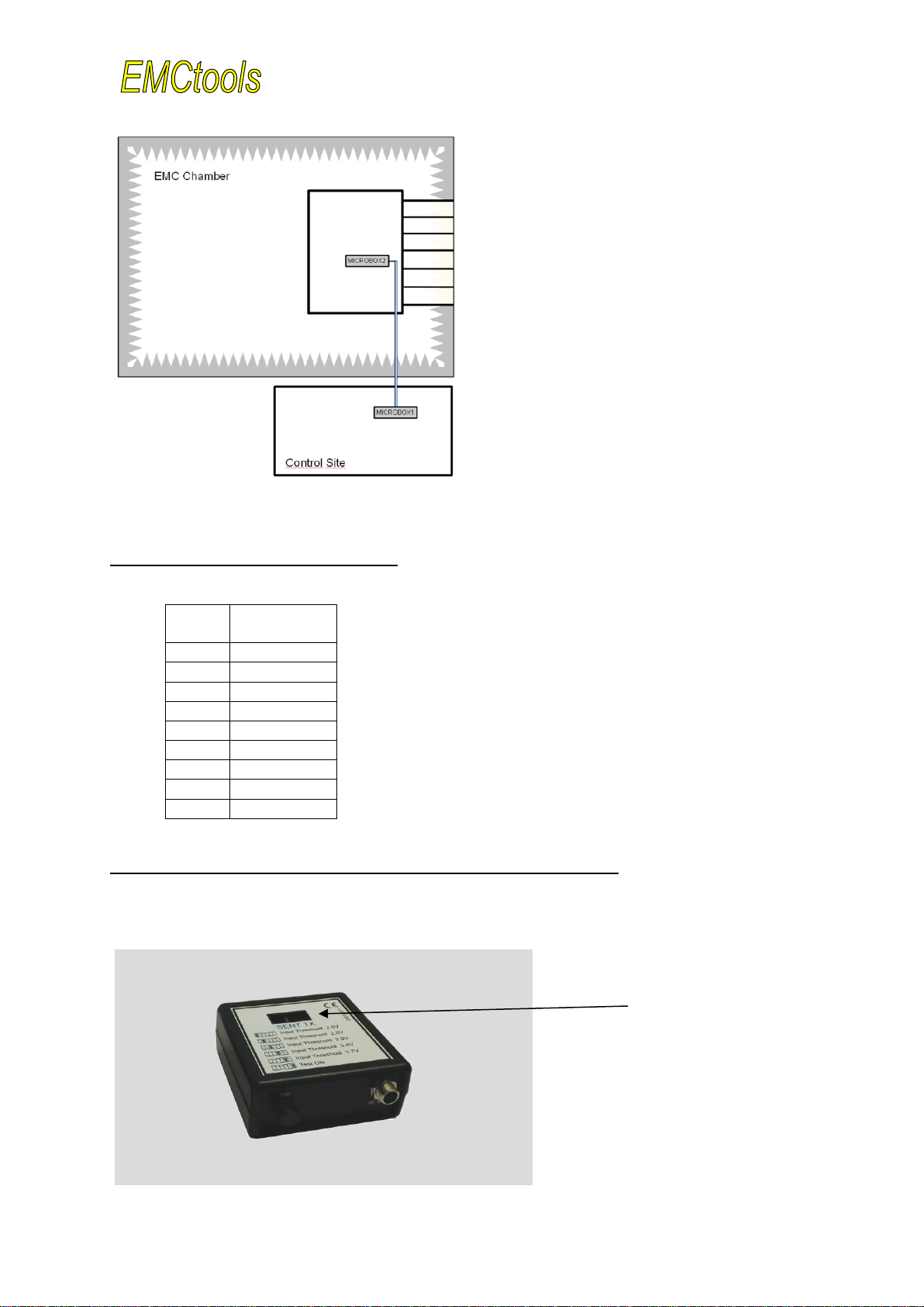
Functional tests e.g. in test-labs often require insulated RS-485 bus installations to control and
monitor the device under test. For this purpose special Fiber Optic RS-485 transceivers are
available. They allow data transmission of RS-485 signals via fiber optic cables and can be used
during susceptibility tests at high field strength levels.
Our EMCtools Microbox has been designed for emission and susceptibility tests. Using multilayer
technology and sophisticated circuit design full RS-485 compatibility and the ability to perform
tests at electromagnetic field levels of 270 V/m and above could be achieved. The handy plastic
housing allows tests with limited test space and a minimum of impact on the field.
The EMCtools Microbox uses standard multimode fiber optic cables and allows direct connection
to the electric bus via SUB-D female connectors.
2. EMCtools Microbox RS-485
The Microbox is built into a handy, rugged plastic housing (65x66x27mm).
Power is supplied externally e.g. by using an external battery or power-supply.
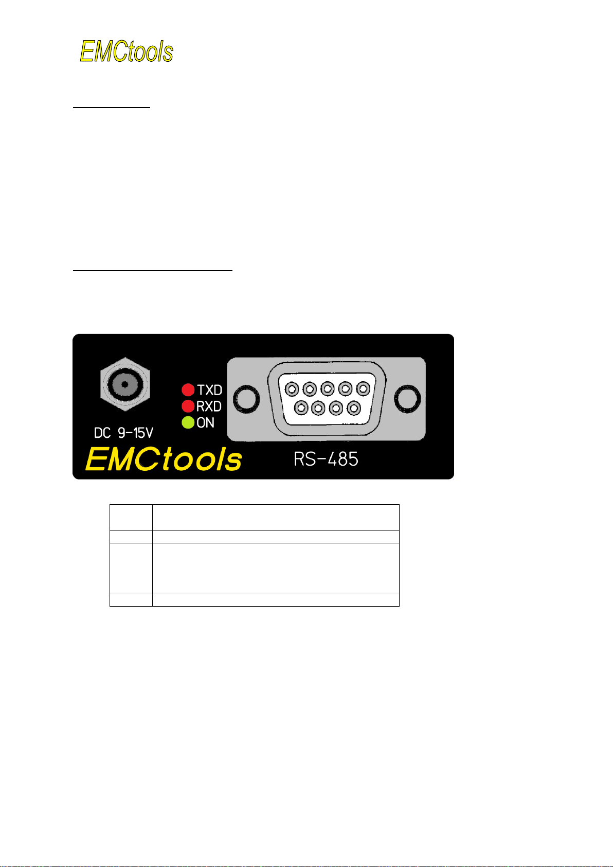
Fig. 1: Front Panel Microbox RS-485
Power supply (DC Power Jack 5.5/2.1mm)
Control-LEDs:
Green: Power on/off status and supply voltage
LED off when supply voltage less than 7V
Red: RXD and TXD (receive and transmit data)
9-pin Sub-D connector for bus-connection
An illuminated green LED (Fig.1 –No.2) indicates the operating status of the Microbox.
A first red LED (Fig.1 –No.2) indicates the status „RXD“ (= receive-data).
It indicates that fiber optic data are received.
A second red LEDs (Fig.1 –No.2) indicates the status of „TXD“ (= transmit-data).
It indicates the transmission of fiber optic data.
The 9-pin Sub-D connector (Fig.1 –No.3) is used to connect the Microbox to the electrical RS-
485-bus. See chapter 4 for pinning details.