Viale Caduti per la Libertà, 4b - 40050 MONTE S. PIETRO - BOLOGNA (ITALY) –
2Tel. 051/6761552 - Fax 051/6760492 - Internet: http://www.emirel.it - E-mail: info@emirelsrl.it – info1@emirelsrl.it
velocità.
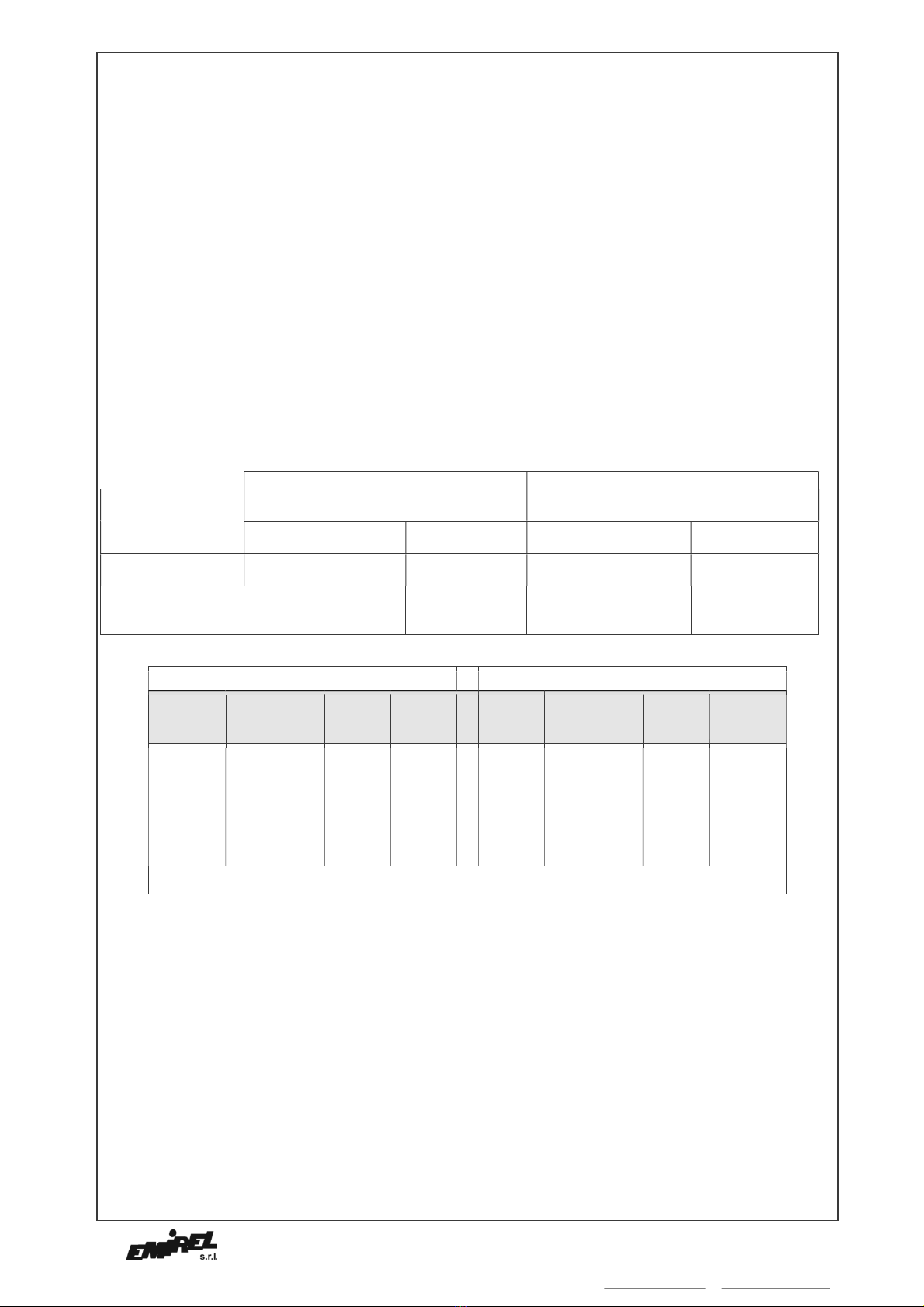
Nella Tab. A sono riportate le gamme ed i cavallotti da
eseguire.
Esempio: (I) veloce= 11A - (I) lenta=2A. Per la veloce si
sceglie la gamma 1,5-15A e si esegue il cavallotto fra i
morsetti 28-31. Per la lenta si sceglie la gamma 0,5-5A e si
esegue il cavallotto 34-38.
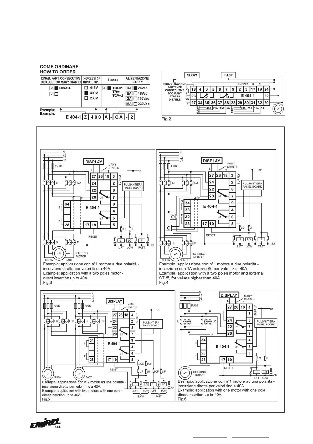
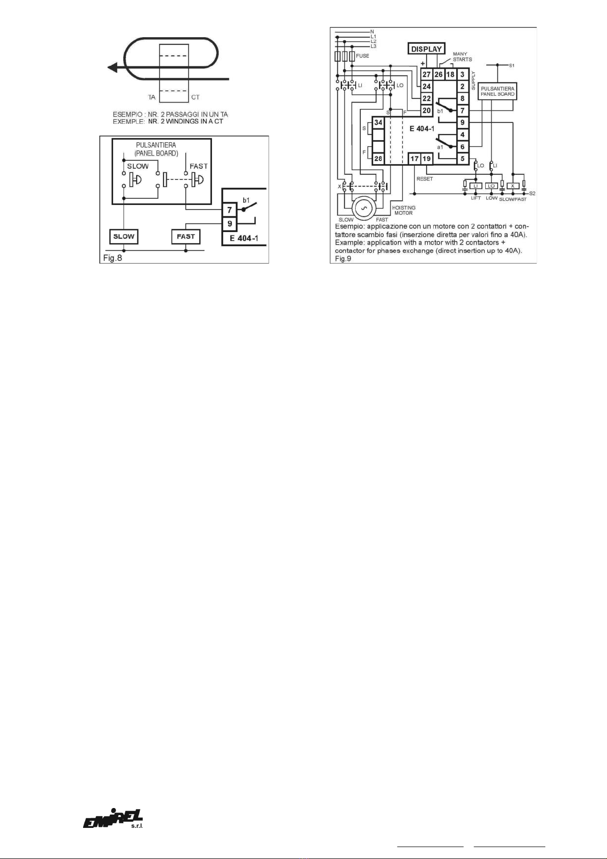
Per le correnti > 40A occorre il TA esterno /5 (v. Fig.4). Nel
foro del dispositivo si farà passare il filo del secondario del
TA esterno, dopo avere eseguito il cavallotto corrispondente
alla gamma 0,5-5A.
Il valore di fondo scala della corrente può essere superato
anche del 30%, purchè il valore dell’uscita analogica (UA)
resti minore di 10Vdc, con il motore a pieno carico. (Se
l’uscita analogica fosse maggiore di 10Vdc, il dispositivo
sarebbe in allarme anche con i set point al massimo).
Esempio: il fondo scala 5A può lavorare anche con corrente
massima di 6,5A.
Le potenze indicate in TAB.A sono per riferimento, in quanto
il fondo scala va scelto in funzione della corrente nominale
assorbita dal motore nelle due condizioni (LENTA e
VELOCE), mentre la potenza dipende anche dalla tensione.
TCL
Tempo di cecità LENTO (0÷1 sec) temporizzatore regolabile
a cacciavite sul frontale. Rende cieca la soglia LENTA
quando si instaura la corrente e permette di superare il
picco di corrente che si presenta all’accensione del motore.
Si attiva tutte le volte che la corrente supera il 10% del
fondo scala della corrente. E’ diviso in 4 parti.
NOTA 2
II numeri 1÷4 riportati per TCL, TR, TCV, non sono secondi !
Indicano le parti in cui é divisa la scala. II fondo scala dei
tempi sono indicati sull’etichetta.
TR
Tempo di ritardo (0÷1 sec) temporizzatore regolabile a
cacciavite sul frontale. E’ attivato dalla fine di TCL; quindi si
somma a TCL ed assieme ritardano l’eccitarsi di RB
(l’eccitazione di RB passerà il motore in VELOCE). E’ diviso
in 4 parti. Durante TR può avvenire l’intervento nella fase
LENTA.
TCV
Tempo di cecità VELOCE (0÷2 sec) temporizzatore
regolabile a cacciavite sul frontale. Rende cieca la soglia
VELOCE quando si instaura la corrente e permette di
superare il picco di corrente che si presenta nella fase
VELOCE. Si attiva tutte le volte che la corrente supera il
10% del fondo scala. E’ diviso in 4 parti.
VISUALIZZAZIONI
ON LED VERDE dispositivo alimentato.
ALED ROSSO ALLARME: indica l’intervento del relè A
per supero di soglia (LENTA o VELOCE)
o per eccesso di partenze.
RIPRISTINO
Avviene alimentando il dispositivo con una tensione
alternata 20÷230Vac fra pin 17 e 19 per almeno 0,5 sec. Si
può utilizzare una tensione continua con il + sul 19.
E’ bene che il ripristino sia abbinato al comando di discesa,
per evitare il sollevamento di carichi eccessivi, sfruttando
più volte la presenza di TCL.
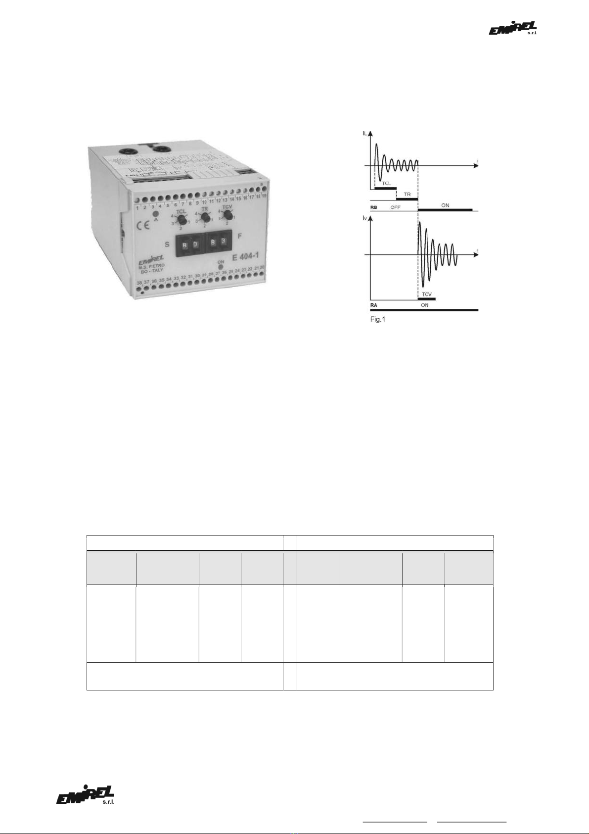
FUNZIONAMENTO
Il dispositivo sarà collegato come da schema di fig.
3,4,5,6,9, per cui il motore partirà sempre in LENTA. Alla
partenza si ha la situazione di fig. 1: durante il TCL non può
avvenire l’ALLARME. Al termine di TCL parte il tempo TR,
durante questo tempo può avvenire l’intervento del RELE’
“A” (PER SUPERO DELLA SOGLIA LENTA IMPOSTATA).
Se non é avvenuto l’intervento, al termine di TR si eccita il
RELE’ “B” che provoca il passaggio da LENTO a VELOCE e
parte il TCV. Durante TCV non può avvenire l’ALLARME.
Al termine di TCV può avvenire l’intervento del RELE’ “A”
per supero della soglia VELOCE (anche il RELE’ “B” cadrà).
NOTA 3
Il dispositivo é dotato di un controllo contro le partenze
troppo frequenti. Se vengono eseguite 9 partenze
Tab A. shows the ranges and the links to be made.
Example: (I) fast= 11A - (I) slow=2A. For the fast, the
range 1,5-15A is selected and the link is made between
the pins 28-31. For the slow the range 0,5-5A is selected
and the link 34-38 is made.
For the currents > 40A the external CT /5 is requested
(see Fig. 4). The CT has 2 pins for the secondary current:
a wire must be connected to one of the 2 pins, must pass
inside the hole of the E 404-1 and must be connected to
the second pin. The motor current may be 30% greater
then full scale value, provided that the analog output is
lower than 10 Vdc, when the motor is charged. If the
analog output is higher than 10Vdc, the device is in alarm
also with the set point at the maximum). Example: the full
scale 5A can work up to a maximum current of 6,5A.
The power values showed in TAB.A. are for reference
only, since the full scale is selected on base of the
nominal current of the motor in the two conditions (FAST
and SLOW), while the power depends also on the voltage
TCL
SLOW Initial timer (0÷1 sec) adjustable by the screwdriver
when the current starts up and avoids the alarm during the
current spike of the motor. It is active every time the
current overcomes the 10% of the current value of full
scale.
It is divided in 4 parts.
REMARK 2
The numbers 1÷4 referred to TCL, TR, TCV are not the
seconds, but they evidence the parts in which the scale is
divided. The full scale of the timers are written on the
label.
TR
Delay timer (0÷1 sec) adjustable by screwdriver on the
front. It is activated by the end of TCL; the two periods are
added to delay the change over of RB relay (when RB
changes over the motor passes to FAST condition). It is
divided in 4 parts. During TR the alarm in the condition
SLOW is allowed.
TCV
Initial timer FAST (0÷2 sec) adjustable by screwdriver on
the front. It bypasses the set point FAST when the current
starts up in order to overcome the current spike appearing
during the FAST condition. It is active every time the
current overcomes the 10% of the current value of full
scale. It is divided in 4 parts.
VISUALIZATIONS
ON GREEN LED Supply on.
ARED LED ALARM: it displays that the relay A has
changed over for set point overcome
(SLOW or FAST) or for too many starts.
RESET
The device resets by applying an alternate voltage,
20÷230Vac, between the pins 17 and 19 for at least 0,5
sec. A direct voltage can be used with + on 19. It is
suggested that the reset is connected with the lowering
command in order to avoid that too heavy loads are lifted
using many times the presence of TCL.
MODE OF OPERATION
The device is connected according to fig. 3,4,5,6,9, and
the motor must starts always from the SLOW condition. At
the start, the condition is as per fig.1: during TCL no
ALARM can take place. At the end of TCL, the period TR
starts, and during this period the “A” RELAY can trip (THE
SLOW SET POINT IS OVERCOME). If the alarm has not
taken place, at the end of TR the “B” RELAY changes over
by turning from SLOW to FAST condition, and TCV starts.
No alarm can take place during TCV. At TCV end, the “A”
RELAY may change over (alarm) due to FAST set point
overcome, and consequently also the “B” RELAY goes off.