EMX Industries IRB-MON2 Manuale utente

IRB-MON2™
Universal UL325 Thru Beam Photoeye
Instruction Manual
The IRB-MON2 thru beam infrared photoeye is an external entrapment protection device type B1,
non-contact sensor for use with automatic gates and doors. The photoeye provides a signal to the gate or
door operator that the beam is, or is not obstructed. It operates up to 115 feet over a
wide range of input voltages (6-35 VDC and 12-24 VAC). The receiver green alignment indicator provides
status information, making set-up and alignment easy. The IRB-MON2 provides compatibility with most
operators that accommodate monitored external entrapment devices per UL325.
Cautions and Warnings
This product is an accessory or part of a system. Install the IRB-MON2 according to
instructions from the gate or door operator manufacturer. Comply with all applicable codes
and safety regulations.
Specifications
Ordering Information
•IRB-MON2-HD – Gray powder-coated metal protective hoods
Operating Range
5 to 115 ft (35 m)
Power
6-35 VDC, 12-24 VAC
on only)
Current (NC and 10K Monitoring Methods)
35 mA DC (when aligned and relay activated)
Current (Pulse Monitoring Methods)
15 mA
Connections
“Removable” screw terminal for easy wiring
Supported Monitoring Methods
10K, 2-wire pulse, Normally Closed (power cycle)
Relay Output Configuration
Form C contacts (NO, COM, NC)
Response Time
<300 mS (for use in NC or 10K monitoring)
Operating Temperature
-40° to 170°F (-40° to 77°C)
Dimensions (L x W x H)
3.6” (91 mm) x 2.9” (74 mm) x 2.9” (74 mm)
Conduit Hole Size (bottom of the housing)
½Inch NPT

Monitoring Methods
UL325 requires continuous monitoring of all safety devices connected to gate and door operators.
Consult the gate or door operator manufacturer’s instruction manual for necessary monitoring
method.
•
Normally Closed (Wiring Diagram A): The operator cycles power to the transmitter while monitoring
the receiver N.C. (Normally closed) contacts for proper operation
•
10K Resistive Termination (Wiring Diagram B): Provides a measurable 10K ohm resistance across
the N.O. (normally open) relay when unobstructed and in Fail Safe mode
•
Two-Wire Pulse, 2 Frequency (Wiring Diagram C): Provides 300Hz “heartbeat” unobstructed,
0Hz obstructed over the receiver input power supply lines
•
Two-Wire Pulse, 3 Frequency (Wiring Diagram D): Provides 300Hz “heartbeat” unobstructed,
2Hz obstructed, and 0Hz when failure is detected, over the receiver input power supply lines
Board Diagram
Sensitivity Potentiometer
Clockwise is maximum sensitivity
Counter-clockwise is minimum sensitivity

mounting screws
Installation
•
Determine the IRB-MON2 mounting location (4-25 inches above the ground).
•
Deactivate the gate or door during photoeye installation.
•
The IRB-MON2 cannot be used for a detection range of less than 5 feet.
1. SET DIPSWITCH FOR MONITORING METHOD:Check the GATE or DOOR
OPERATOR manual (or call the operator company) to determine which
monitoring method is necessary for your operator. Remove the front
covers (remove 4 plastic screws in each unit), and then set IRB-MON2
dipswitches per pages 4 & 5 for the needed operator monitoring method.
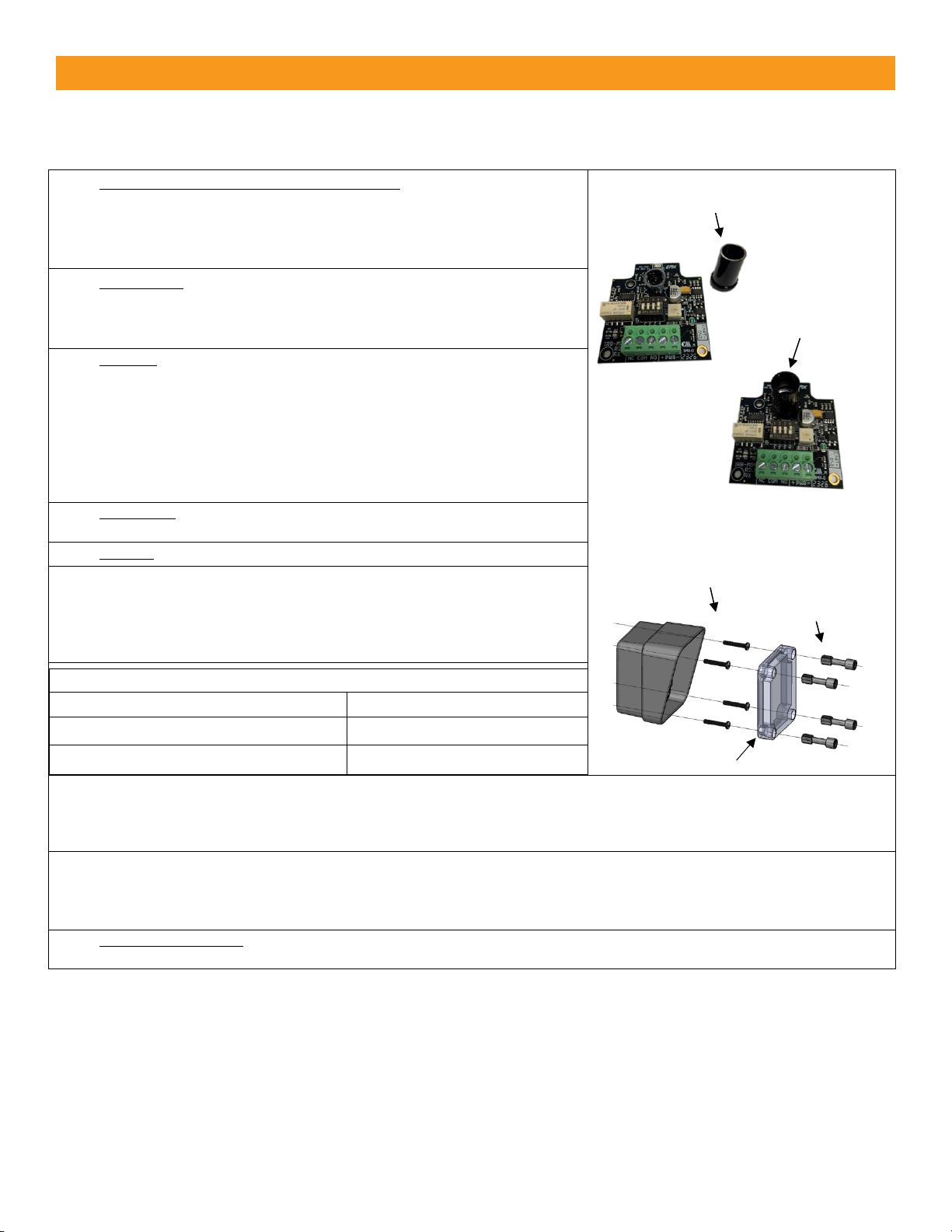
2. MOUNTING: Determine your mounting height from 4 to 25 inches above
the ground, and mount the housings using 4 screws (not supplied) that go
through the inside of the housing, inside of the 4 holes in the corners
(same holes where the plastic screws came out of).
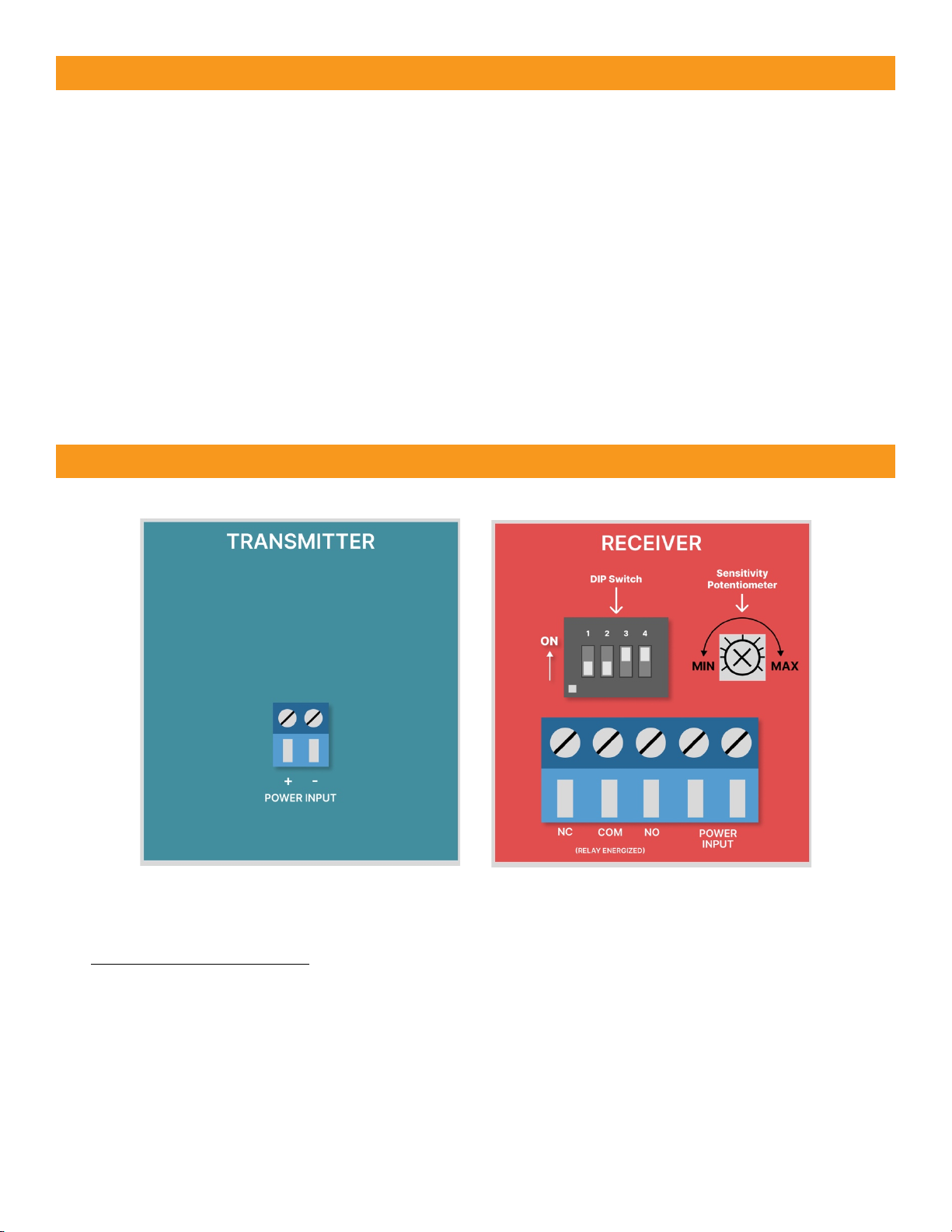
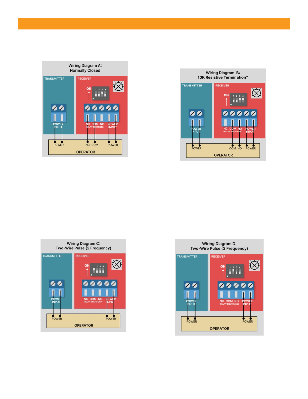
3. WIRING:Connect 6-35 VDC or 12-24 VAC to the “Power Input” terminals
on the transmitter (marked “+ -”) and receiver (marked “PWR”). Remove
(pull up on) the green screw terminals for ease of wiring. Wire according
to the page 5 diagram that corresponds to your operator monitoring
method. Wiring must enter via UL listed watertight conduit fitting such as
a ½” watertight conduit connector, through the bottom of the housing.
NOTE: MUST USE 6-35 VDC FOR PULSE MONITORING.
4. OPTIONAL: Install optional sunshield over the receiver reflector to reduce
the effects of sun interference or cross talk.
5. POWER: Apply power to the IRB-MON2 transmitter and receiver.
6. ALIGNED CORRECTLY: The receiver and transmitter are aligned when the
RECEIVER green LED is on “solid”. Once on solid, then slowly decrease the
sensitivity setting on the receiver (turn potentiometer counter clockwise)
until the receiver green LED just starts to flash. Now, increase sensitivity
setting “one quarter” turn clockwise. Confirm receiver LED is still on solid.
7.
LED Indicators
Transmitter - Green LED on
Power
Receiver - Green LED on solid
Aligned
Receiver - Green LED flashing
Beam blocked or not aligned
8. TEST OBSTRUCTION: Place an obstruction (ex. hand) between the transmitter and receiver -- The receiver green LED
should start flashing. Check the operator control board and verify the safety input is recognized by the operator. Test the
beam with an obstruction between transmitter and receiver at multiple distances to confirm proper operation.
9. REMOVE OBSTRUCTION: Remove the obstruction and the receiver green LED will turn on solid.
TIP: If the IRB-MON2 is aligned but not detecting an obstruction, slowly reduce the receiver sensitivity (counter-clockwise)
until the obstruction is detected. This may be applicable for installations with a detection zone of less than 20 ft.
10. SECURE THE COVERS: Secure the covers using all four plastic screws provided (do not over tighten the screws but make
them snug). Done!
Optional sunshield
Sunshield installed
plastic cover screws
cover

•FAIL SAFE (Wiring Diagram A or B) – Most common monitoring method - Gate opens with loss of
power - DIP switches shown as in the table above for monitored “Normally Closed” or “10K Resistive
Termination”. The relay will change state during a loss of power (N.C. will open, and N.O. will close).
NOTE: Use this mode in all normal operations and UL325 monitoring scenarios.
•FAIL SECURE (Wiring Diagram A or B) – Less common monitoring method, Gate closes/secures
with loss of power - To achieve Fail Secure for either “Normally Closed” or “10K resistive
termination”, configure dipswitches the same as shown in the above table “EXCEPT” SW1 needs to be
ON. The relay will function opposite what is written on the PCB. When powered on and aligned the
N.O. relay will be closed, and the N.C. contact will be open. The relay WILL NOT change states during
loss of power so the gate stays closed during power loss (N.O. will close, and N.C. will open).
•Two-Wire Pulse Monitoring (Wiring Diagram C or D) – Must use 6-35 VDC (can’t use AC power in
two-wire pulse mode) and requires a compatible operator board with the current limiting circuitry.
Note: If using the IRB-MON in an application that requires Normally Open, but does not require a
10K resistor across the normally open contact then wire according to diagram B with dispswitch
SW4 set to OFF.
Monitoring
Method
Wiring
Diagram
DIP Switch Settings
Output
Connections
10K
State
SW1
SW2
SW3
SW4
Normally Closed
A
OFF
OFF
ON
OFF
NC, COM
10K
DISABLED
10K Resistive
Termination
B
OFF
OFF
ON
ON
NO, COM
10K
ENABLED
Two-Wire Pulse
(2 Frequency:
300Hz, 0Hz)
C
ON
OFF
OFF
OFF
DC POWER
N/A
Two-Wire Pulse
(3 Frequency:
300Hz, 2Hz, 0Hz)
D
OFF
ON
OFF
OFF
DC POWER
N/A
Configuration Settings

Wiring Diagrams
Wire Diagram A: Normally Closed
Wiring Diagram B:
10K Resistive Termination
Wiring Diagram C:
Two-Wire Pulse (2 Frequency)
Wiring Diagram D:
Two-Wire Pulse (3 Frequency)
*If you need a normally open relay, but
without a 10K resistor then set Dipswitch
4 to OFF. This is a non-monitored method.

Warranty
EMX Industries, Inc. products have a warranty against defects in materials and workmanship for a period
of two years from the date of sale to our customer.
Symptom
Possible Cause
Solution
Does not detect obstruction
Sensitivity is too high
Signal is reflecting off another
surface
Decrease sensitivity
potentiometer counter-
clockwise
Check area for highly reflective
surfaces
Receiver green LED flashes
continuously, indicating an
obstruction when one is not
present
Sensitivity is too low
Transmitter does not have
power
Receiver does not “see”
transmitter
Increase sensitivity
potentiometer clockwise
Check power source of
transmitter
Make sure transmitter and
receiver are aligned
Receiver activates but does not
transmit signal to operator
Faulty connection between
receiver and operator control
input
Verify all wires and terminal
connections
Receiver green LED off
Transmitter too close to receiver
Decrease sensitivity
(potentiometer counter-
clockwise)
Increase distance between
transmitter and receiver
Output relay chatters constantly
between open and close
All 4 DIP switches are in the OFF
position
Operator expects Diagram C or
D but dipswitches are configured
according to Diagram A or B on
page 4
Troubleshooting
Indice
Altri manuali EMX Industries Sensore di sicurezza

EMX Industries
EMX Industries RAVEN Manuale utente

EMX Industries
EMX Industries USVD-4X Manuale utente

EMX Industries
EMX Industries OWL Manuale utente

EMX Industries
EMX Industries Ultra II DTEK Manuale utente

EMX Industries
EMX Industries VMD202 Manuale utente

EMX Industries
EMX Industries VMD202 Manuale utente

EMX Industries
EMX Industries ULT-MVP Manuale utente

EMX Industries
EMX Industries ULT-V2 Manuale utente

EMX Industries
EMX Industries MVP D-TEK Manuale utente

EMX Industries
EMX Industries CarSense 202 Manuale utente


