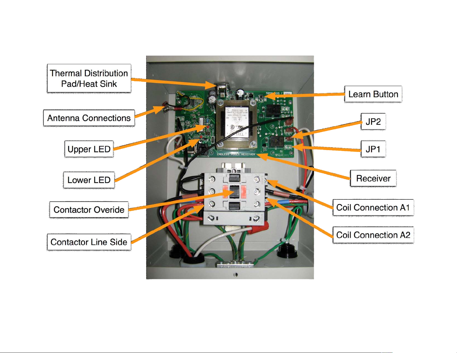
Wireless Controller (EP1 or EP2) 60Hz
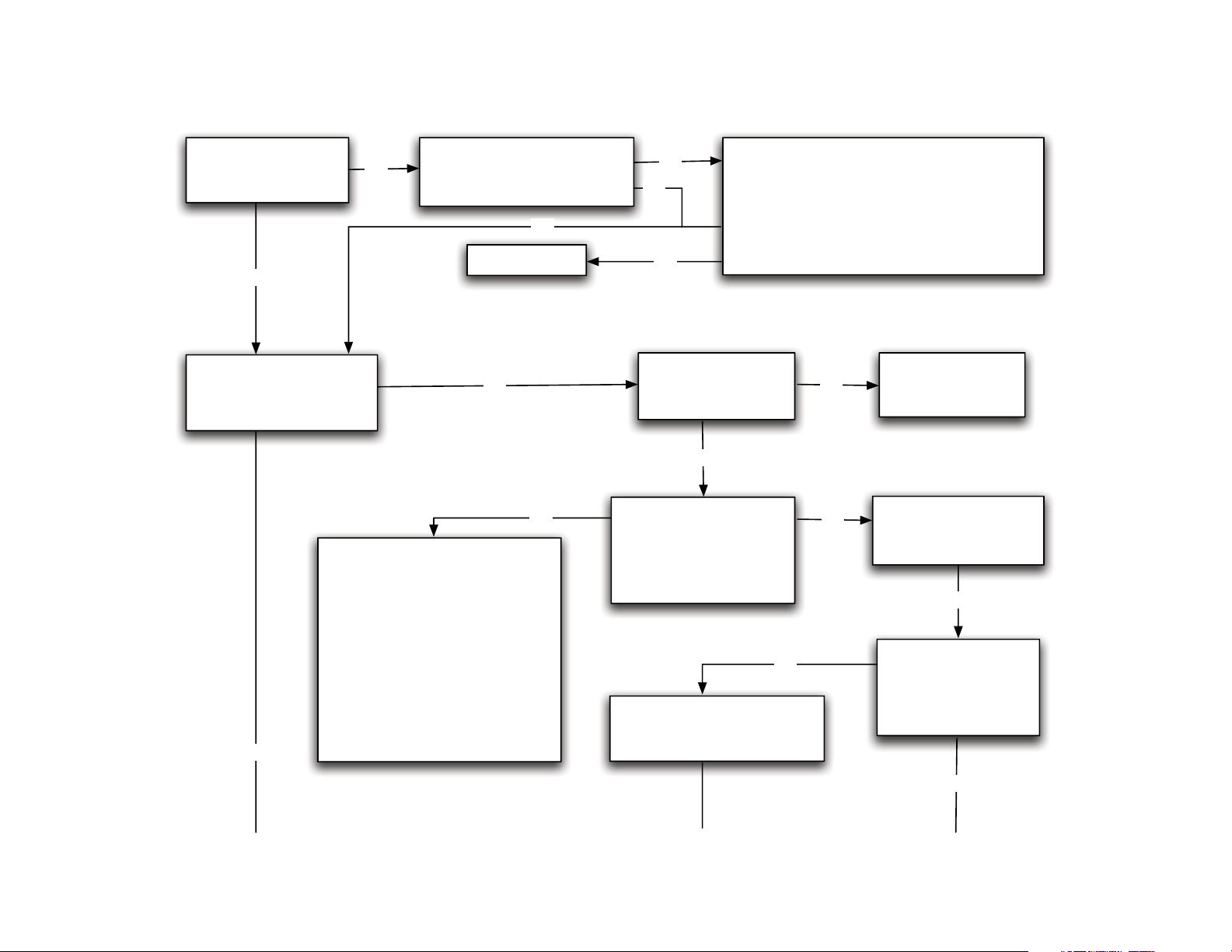
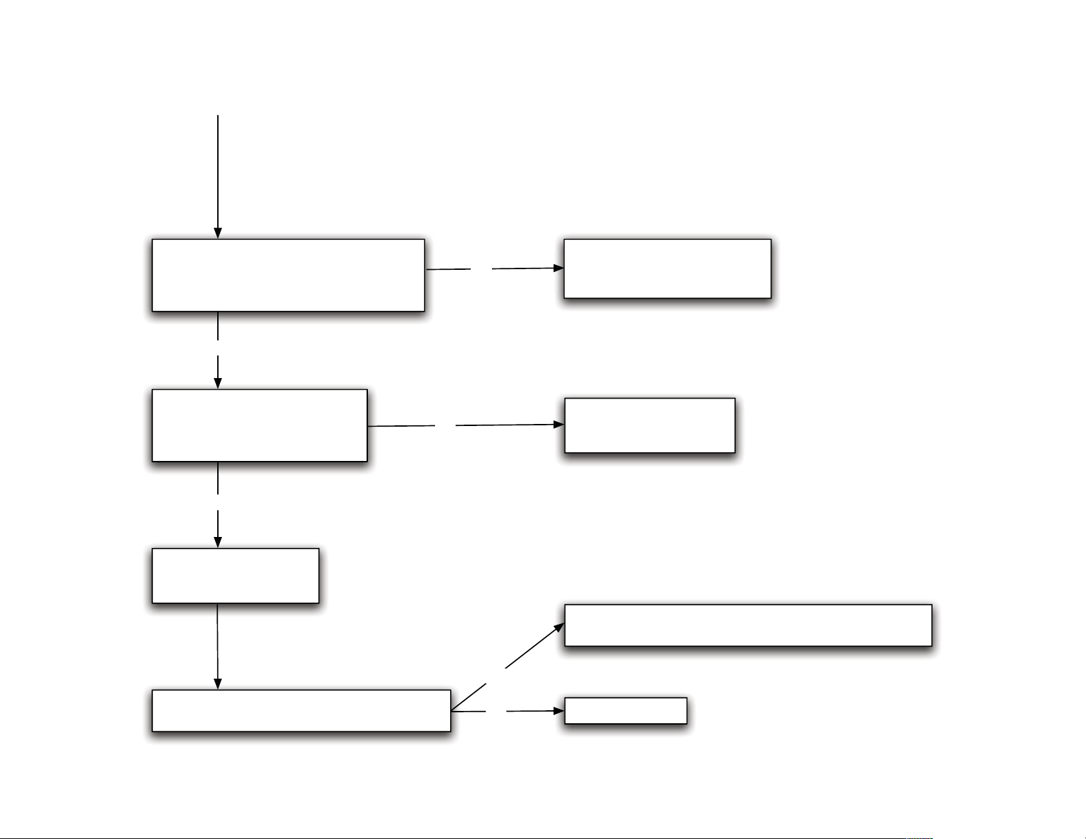
Power Unit Not Turning On
Does the unit run when
the contactor override is
depressed?
Install jumper wires
(10 gauge)
Is jumper wire installed on
line side of contactor between
2 & R2 and 4 & R4?
Verify input voltage to contactor;
- Does Line 1 to ground = 110V?
- Does Line 2 to ground = 110V?
- Does Line 1 to Line 2 = 220V?
Verify wiring of entire
controller using schematic
on controller
Faulty wire connection or
breaker on line side. Have
electrician check.
NY
Y
N
N
Has the reservoir been
filled with hydraulic fluid
(within 2" of reservoir top)
Fill reservoir to within 2" of top
NOTE: turn off breaker prior to filling
Was reservoir topped off after the
initial running of the power unit?
Fill reservoir to within 2" of top
NOTE: turn off breaker prior to filling
Y
Y
N
N
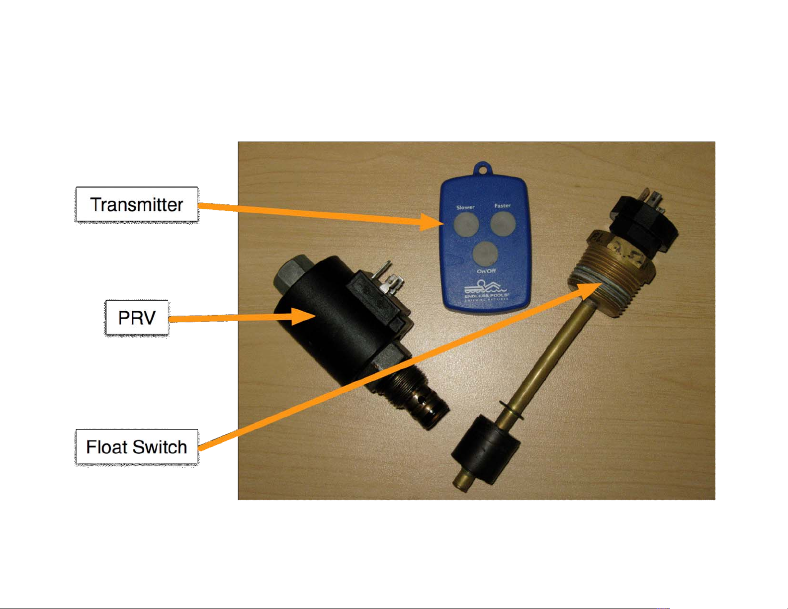
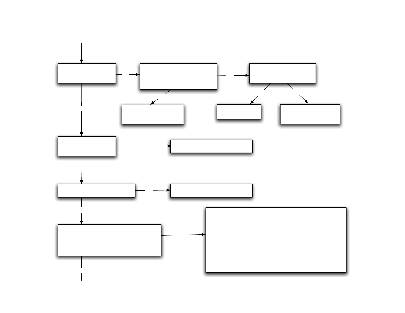
Test the float switch for continuity by measuring
between the (2) parallel spades.
Ensure that the spade connections on float
switch are not broken or bent over.
Is there continuity on the float level switch?
Shim up power unit under opposite corner from float switch to
push more fluid towards float switch location.
If still no continuity, then remove float switch and test;
1. Remove black square cord end from switch
2. Place wrench on the large brass colored collar of float switch
3. Float must be in "up" position to test
If still no continuity, replace float switch.
NOTE: to allow unit to operate until replacement switch arrives,
bypass float switch with jumper wire in controller, check system
for leaks and leave jumpered. Remove jumper wire when
replacement float switch is installed.
N
Y
Y