5016-564-B0-001, Rev. B (10/2023)
Table of Contents
Safety Notes......................................................................................................................................................................... 2
Unpacking and Inspection.................................................................................................................................................. 6
General Safety Precautions ................................................................................................................................................ 6
Electrical Safety ................................................................................................................................................................... 7
Mechanical Safety ............................................................................................................................................................... 7
1.0 Overview and Specifications................................................................................................................................. 8
1.1 The Alpha®APX3/APX3-G Series Non-standby Power Supply..................................................................... 8
1.2 Alpha®APX3/APX3-G Series Non-standby Power Supply Specifications....................................................10
1.3 Operating Principle .....................................................................................................................................11
1.4 Operation....................................................................................................................................................12
2.0 Installing an Alpha®APX3/APX3-G Unit............................................................................................................. 13
2.1 Enclosure Grounding ..................................................................................................................................13
2.2 Pole-mount Installations .............................................................................................................................14
2.2.1 Wooden, Steel or Concrete Pole Mounting Procedure..................................................................14
2.3 Wall Mount Installations .............................................................................................................................15
2.4 Connecting an Alpha®APX3/APX3-G Unit ..................................................................................................16
2.4.1 AC Output Connection...................................................................................................................16
2.4.2 Utility Power Connection ...............................................................................................................17
2.4.3 External Service Disconnect..........................................................................................................17
3.0 Initial Startup ........................................................................................................................................................ 18
4.0 Troubleshooting and Repair ................................................................................................................................ 19
4.1 Troubleshooting Guide................................................................................................................................19
4.2 Important Repair Instructions .....................................................................................................................19
4.3 Parts, Ordering, and Warranty Information .................................................................................................19
4.3.1 Ordering and Warranty ..................................................................................................................19
4.3.2 Replacement Parts ........................................................................................................................20
4.4 System Block Diagram............................................................................................................................... 20
Figures
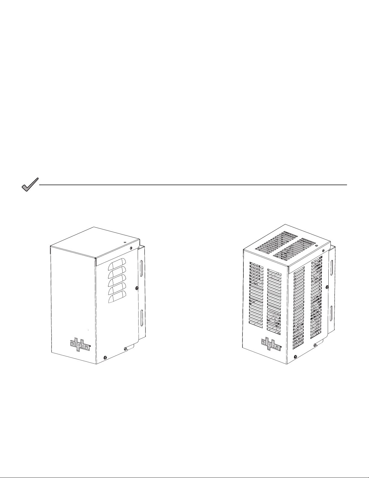
Fig. 1-1, Alpha®APX3/APX3-G Series Non-standby Power Supply (Front View) .................................................................... 8
Fig. 1-2, Alpha®APX3-G Series Non-standby Power Supply, Vented Indoor Configuration (Front View)................................ 8
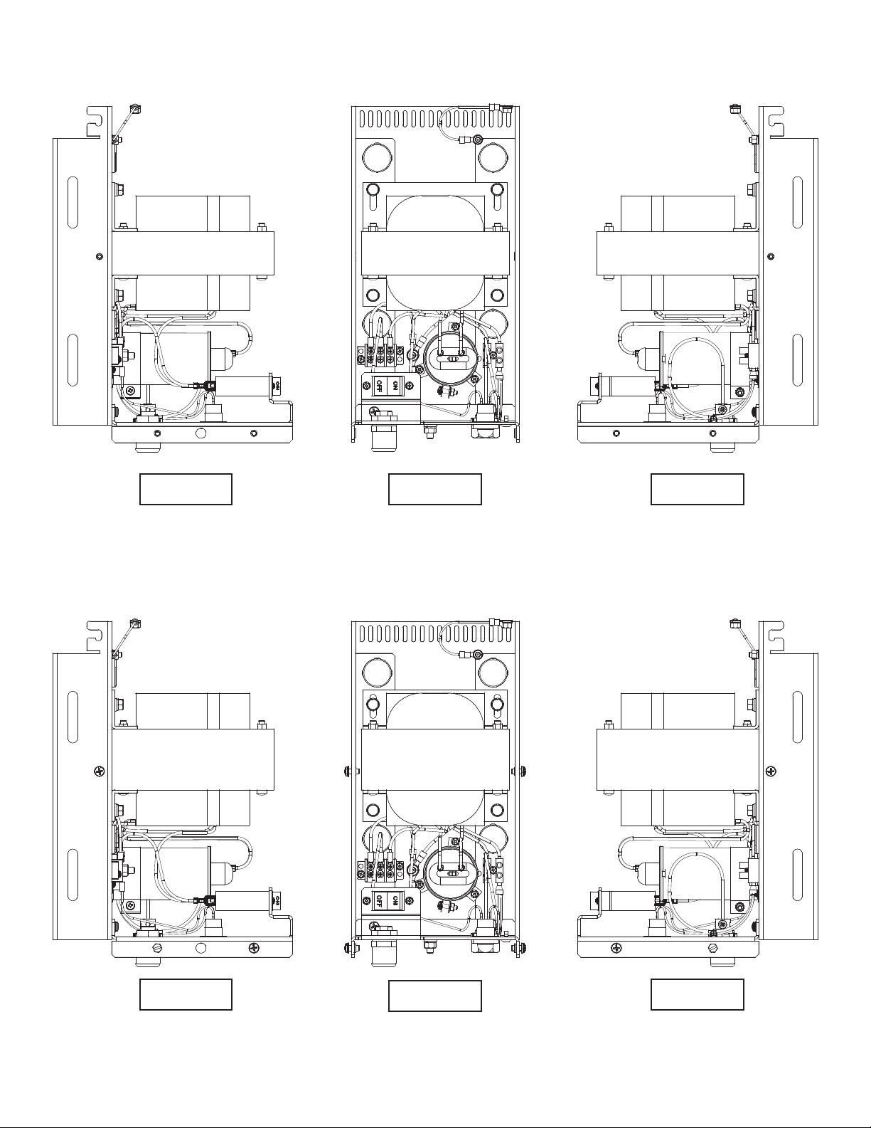
Fig. 1-3, Alpha®APX3 (6014)/APX3-G (608G) Non-standby Power Supply (Without Cover)................................................... 9
Fig. 1-4, Alpha®APX3-G (615G) Non-standby Power Supply (Without Cover) ....................................................................... 9
Fig. 1-5, Ferroresonant ‘Tank’ Circuit and Resulting Output Waveform ................................................................................12
Fig. 1-6, Alpha®APX3/APX3-G Non-standby Power Supply Operational Controls ................................................................12
Fig. 2-1, Grounding Enclosure ..............................................................................................................................................13
Fig. 2-2, Pole-mounted Alpha®APX3/APX3-G Unit ...............................................................................................................14
Fig. 2-3, Wall-mounting Holes on Alpha®APX3/APX3-G Unit ...............................................................................................15
Fig. 2-4, Sealing Plug Locations (Cover Removed) ...............................................................................................................15
Fig. 2-5, Seizure Screw Location ..........................................................................................................................................16
Fig. 2-6, Stinger Pin ..............................................................................................................................................................16
Fig. 2-7, Connecting to Output Coaxial Connector................................................................................................................16
Fig. 2-8, Utility Power Input and AC Output Connections.....................................................................................................17
Fig. 3-1, Voltage Reading Locations......................................................................................................................................18
Fig. 4-1, Alpha®APX3-G Non-standby Power Supply System Block Diagram...................................................................... 20
Fig. 4-2, Alpha® APX3-6014 Non-standby Power Supply System Block Diagram................................................................. 21
Tables
Table 1-1, Alpha®APX3/APX3-G Series Non-standby Power Supply Specifications..............................................................10
Table 4-1, Alpha®APX3/APX3-G Non-standby Power Supply Replacement Parts ............................................................... 20