Engineered air EngA W-TRAC Manuale utente

IOM‐49 Mar99R4
INSTALLATION, OPERATION
AND MAINTENANCE MANUAL
FOR
W-TRAC
HEAT WHEEL CONTROLLER
UNIT MODEL NO. _________________
UNIT SERIAL NO. _________________
SERVICED BY: ___________________
TEL. NO: ________________________
CANADIAN
HEAD OFFICE
AND FACTORY
USA
HEAD OFFICE
AND FACTORY
CANADIAN
EASTERN FACTORY
1401 HASTINGS CRES.
SE
CALGARY, ALBERTA
T2G 4C8
Ph: (403) 287-4774
Fx: 888-364-2727
32050 W. 83r
d
STREET
DESOTO, KANSAS
66018
Ph: (913) 583-3181
Fx: (913) 583-1406
1175 TWINNEY DRIVE
NEWMARKET,
ONTARIO
L3Y 5V7
Ph: (905) 898-1114
Fx: (905) 898-7244
SALES OFFICES ACROSS CANADA AND USA
Retain instructions with unit and maintain in a legible condition.
Please give model number and serial number when contacting
Engineered Air for information and/or parts.
www.engineeredair.com

A
IOM‐49 2of12 Mar99R4
W‐TRAC
IfanyerrorsoromissionsarenotedpleasecontactthenearestEngineeredAirTechnicalService
Department.
Toensurewarrantyishonored,onlyqualifiedpersonnelshouldbeemployedforserviceand
troubleshooting.IffurtherinformationisrequiredpleasecontactthenearestEngineeredAiroffice.
Therearetwosetsofelectricaldrawingandunitfunctionsheetsprovidedwiththeappliance.Onesetisin
anenvelopewhichalsocontainstheOperation,InstallationandMaintenancemanual(s).Thispackageis
forcopying,thenshouldeitherbereturnedtotheapplianceorstoredinasafeplace.Theothersetis
attachedtothecontrolpaneldoorandshouldneverberemoved.
Pleasereportanyomissionstothenationalservicemanager.
Warning:
Improperinstallation,adjustment,alteration,serviceormaintenancecancause
propertydamage,injuryordeath.Readtheinstallation,operatingand
maintenanceinstructionsthoroughlybeforeinstallingorservicingthisequipment.
Warning: Thisunitisconnectedtohighvoltages.Electricalshockordeathcouldoccurif
instructionsarenotfollowed.Thisequipmentcontainsmovingpartsthatcanstart
unexpectedly.Injuryordeathcouldoccurifinstructionsarenotfollowed.All
workshouldbeperformedbyaqualifiedtechnician.Alwaysdisconnectandlock
outpowerbeforeservicing.DONOTbypassanyinterlockorsafetyswitchesunder
anycircumstances.

AW-TRAC
IOM‐49 3of12 Mar99R4

AW-TRAC
IOM‐49 4of12 Mar99R4
TableofContents
INTRODUCTION..................................................................................................................................................5
CONTROLLERRATINGS......................................................................................................................................5
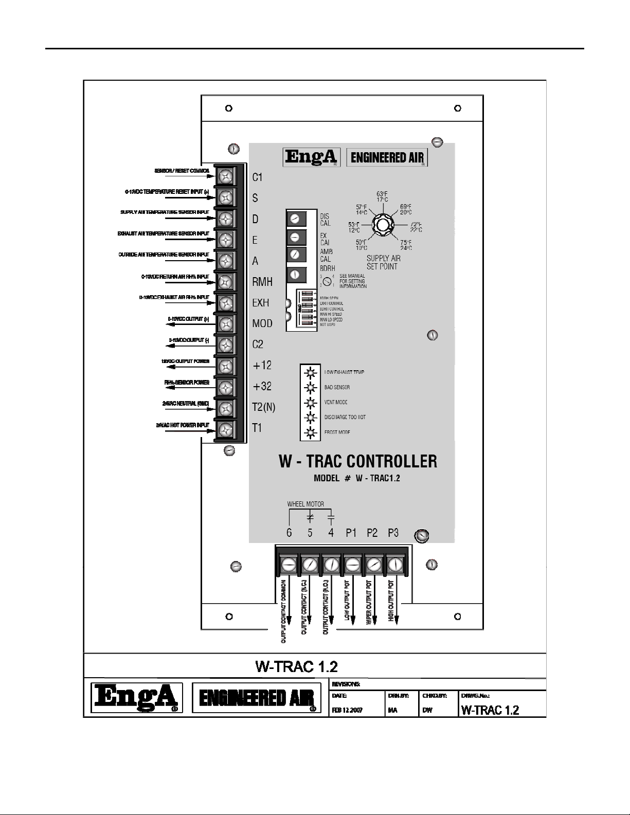
CONTROLLERDESCRIPTION...............................................................................................................................6
TERMINALLIST...................................................................................................................................................6
DIPSWITCHES....................................................................................................................................................6
INDICATIONANDDIAGNOSTICLIGHTS..............................................................................................................7
ADJUSTMENTPOTS............................................................................................................................................7
TEMPERATURECONTROL..................................................................................................................................7
BASESETPOINT..................................................................................................................................................8
SETPOINTRESET.................................................................................................................................................8
FROSTCONTROL................................................................................................................................................8
EXHAUSTAIRRH%SENSOR...............................................................................................................................8
RETURNAIRRH%SENSOR.................................................................................................................................9
BDRHPREDICTEDRETURNAIRRELATIVEHUMIDITY........................................................................................9
WIRING...............................................................................................................................................................9
SENSORTABLE.................................................................................................................................................12
SERVICENOTES................................................................................................................................................10
ROTATION........................................................................................................................................................10
MOTORSPEEDCONTROL.................................................................................................................................10
KBVF/SIVF(R)..................................................................................................................................................10
WHEELROTATIONSPEED................................................................................................................................11
SENSORCALIBRATION.....................................................................................................................................11
DISCHARGETEMPERATURECALIBRATION......................................................................................................11
EXHAUSTTEMPERATURECALIBRATION..........................................................................................................11
HUMIDITYSENSORS.........................................................................................................................................12

AW-TRAC
IOM‐49 5of12 Mar99R4
INTRODUCTION
TheW‐TRACisasupervisorycontrollerforEngineeredAirHRWheatwheels,withbuiltindischargeair
temperaturecontrolandoptionalexhaustfrostcontrol.
Theinformationusedinthismanualshouldbeusedinconjunctionwiththeunitfunctionsheet(s)andthe
HRWseriesInstallation,Operation,andMaintenancemanual.
TheW‐TRACisdesignedtocontrolonlyEngineeredAirequipment.Variousupgradesandimprovements
havebeenmadeovertime.Alwaysincludeanysuffixlettersandnumbersfortroubleshootingand/or
replacement.AllW‐TRACmodelsarebackwardscompatible;howeversomeadditionalwiringmaybe
required.
Note:Itisnecessarythatalloftheremotewiringandcontrolsbecompleteandoperationalbeforestarting
theappliance.
CONTROLLERRATINGS
Powerrequirements:24VAC,40VA.
ContactRating:120V3Ainductive
0‐10Vdcinputimpedance:5k
Environment:‐40to120°F(‐40to50°C)non‐condensing.

AW-TRAC
IOM‐49 6of12 Mar99R4
CONTROLLERDESCRIPTION
TERMINALLIST
Terminal Description
C1 Sensorcommon,and0‐10Vdcresetcommon(‐).
S 0‐10Vdctemperatureresetinput(+).
D Supplyairtemperaturesensorinput.
E Exhaustairtemperaturesensorinput.
A Outsideairtemperaturesensorinput.
RMH 0‐10VdcreturnairRH%input.
EXH 0‐10VdcexhaustairRH%input.
MOD 0‐10Vdcheatwheelcontroloutput(+).
C2 0‐10Vdcheatwheelcontroloutput(‐).
+12 12Vdcoutputpower
+32 32Vdcoutputpower(RH%sensorhot)
T2(N) 24VacNeutralpowerinput.
T1 24VacHotpowerinput.
6 Outputcontactcommon
5 Outputcontactnormallyclosed(N.C.)
4 Outputcontactnormallyopen(N.O.).Startcontact.
P1 Lowoutputpotentiometer(legacy,foroldstyleDCdrivemotors).
P2 Wiperoutputpotentiometer(legacy,foroldstyleDCdrivemotors).
P3 Highoutputpotentiometer(legacy,foroldstyleDCdrivemotors).
DIPSWITCHES
W‐TRACconfigurationoptionsareconfiguredbyDIPswitchselection and/or wiring connections. These
arefactorysetandshouldnotnormallyneedtobealtered.
DIPSW Description
BDRHSPEN ‘ON’whenRH%sensingofthereturnairisnotused.W‐TRACwillcontrolbasedon
pre‐definedRH%values.Switchwillbe‘OFF’whensensingactualRH%.
EXRHCTRL ‘ON’whenusingexhaustairRH%sensing.
BDRHCTRL ‘ON’whenRH%sensingofthereturnairisnotused.Switchmustbeinthesame
positionasBDRHSPEN(above).
MANHISPEED* ‘ON’todrivetheoutputtomaximumwheelrotationspeed.
MANLOSPEED* ‘ON’todrivetheoutputtominimumwheelrotationspeed.
*Donotenablebothswitchesatthesametime,orleaveeitherswitch‘on’innormaloperation.

AW-TRAC
IOM‐49 7of12 Mar99R4
INDICATIONANDDIAGNOSTICLIGHTS
OnthefaceoftheW‐TRACare5redLEDindicationlights.
Light Description
LowExhaust
Temp
Indicatestheexhausttemperatureisbelowthecalculatedminimumallowable
temperature,whichisbasedontheamountofmoistureinthereturnair(measured
orestimated)andtheambienttemperature.
BadSensor Shortedoropensensorindication.
VentMode Wheelwillbestopped.Nocallforheatingorcooling.
DischargeTooHot Wheelisslowingdownduetoexcessiverecoveryofheat.
FrostMode Heatwheelrotationspeedisreducingtopreventfrostaccumulation.
ADJUSTMENTPOTS
Thereareanumberofsettingandcalibrationpotentiometers(POT’s)locatedonthefaceoftheW‐TRAC.
Modificationstotheseshouldonlybedonebyexperiencedandqualifiedpersonnel.
POT Description
DISCAL Dischargetemperaturesensorcalibration.
EXCAL Exhausttemperaturesensorcalibration.
AMBCAL Ambient/outdoortemperaturesensorcalibration.
BDRH PredicteddesignreturnairRH%scale(1‐4).
TEMPERATURECONTROL
TheW‐TRAChas4modesofoperation;Heat,Defrost,VentandCool,thatcontrolsthewheelrotational
speedtoachievethedesiredtemperaturesetpointofsupplyairleavingthewheel.
Whentheoutsideairiscolderthantheexhaustair,theheatwheelwillrotatetocaptureheatfromthe
exhaustairsideandtransferittothesupplyairstream.Increasingtherotationspeedwillincreasethe
amountofheattransferred.
Iftoomuchheatisbeingremovedfromtheexhaustairstreamitispossibleforfrosttoaccumulateonthe
faceoftheheatwheel.TheW‐TRACwillautomaticallyreducetherotationspeedtopreventfrosting.
Ifnoheatingisrequired,theW‐TRACwillstopthewheelrotationandenter‘ventmode’.

AW-TRAC
IOM‐49 8of12 Mar99R4
IftheoutsideairtemperatureiswarmerthantheexhaustairtheW‐TRACwillenter‘coolmode’and
rotatetheheatwheeltotransferheatfromtheoutsideairtotheexhaust.
BASESETPOINT
TheW‐TRACisdesignedtobeadischargeairtemperaturecontroller.Thebasedischargeairtemperature
issetfromthesetpointcontrolknoblocatedonthefaceoftheW‐TRAC.
SETPOINTRESET
Thebasedischargeairtemperatureisoftenmodifiedfromaremotesignaltomaintainthedesired
temperatureofthesuppliedspace.Thisiscalledreset.TheW‐TRACdischargetemperaturecanbereset
fromavarietyofsourcesusinga0‐10VDCsignal.
AnoffsettotheBMSinputrangecanbeimplementedbyaddinga7.5kresistorinserieswithterminalS.
Thefollowingtabledescribesthechangeofdischargesetpointfromtheinputvoltage(toterminalsS+and
C1‐),withasetpointfixedat66°F.Refertotheequipmentfunctionpageforthedesignresetrange.
InputVoltage
0.0 2.0 4.0 6.0 8.0 10.0
Discharge
Setpoint(°F/°C)
NoResistor 30/‐1 40/4 45/7 52/11 60/15 66/19
7.5kResistor 48/9 53/12 56/13 59/15 63/17 66/19
FROSTCONTROL
Frostshouldnotbeallowedtobuilduponthewheel.Itisnecessarytoreducetheamountofheat
recoveredwhentheoutsidetemperatureisbelowthefreezingpoint(0°C/32°F)andtheexhaustleaving
temperaturefallstoapointthatfrostcanbegintoform.Frostmaydamagethewheelandreduceairflow.
Operatingtheheatwheelclosetothefrostthresholdtemperaturewillprovidemaximumenergyrecovery.
Thereare3differentmethodsofprovidingfrostcontrol,allofwhichreducetheheatwheelrotation
speed.
EXHAUSTAIRRH%SENSOR
ThismethodofcontrolrequiresahumiditysensorconnectedacrossterminalsEXHandC2.DIP1and3
mustbeOFF,DIP2mustbeON.Thesensorisinstalledintheexhaustairsection,justaftertheheat
wheel.

AW-TRAC
IOM‐49 9of12 Mar99R4
Whentheoutdoorambienttemperatureisbelow15°F(‐10°C)thespeedoftheheatwheelwillbereduced
tomaintaintheleavingexhaustairhumiditybetween80–90%.Thisapplicationrequireshighaccuracy
humiditysensors.
RETURNAIRRH%SENSOR
ThismethodoffrostcontrolrequiresaRHsensorinstalledintheequipmentreturnairsection,justbefore
theheatwheel,wiredintoterminalsRMHandC2.DIP3mustbeON,DIP1and2mustbeOFF.
UsingthevaluesoftheRHandambient(outsideair)sensor,theW‐TRACcalculatestheminimum
allowableexhaustairtemperaturethatwillkeepfrostfromformingonthewheel.
BDRHPREDICTEDRETURNAIRRELATIVEHUMIDITY
RH%sensingisnotusedinthismethodoffrostcontrol.DIP1and3mustbeON,whileDIP2isOFF.
TheW‐TRACmayoperatewithouttheuseofhumiditysensinginsituationswheretheRH%valuesare
expectedtobereasonablyconstant.Inthesecases,theW‐TRACoperatesbysensibletemperatureonly.
Whenenabled,theBDRHpot(BuildingDesignRelativeHumidity)issetaccordingtotheexpecteddesign
returnairconditions.RefertothetablebelowtosettheexpectedvaluesbasedontemperatureandRH%.
Table1
BDRHsetting ReturnAirConditions
70°F(21°C) 75°F(24°C) 80°F(27°C)
1 <25% <21% <18%
2 26–32% 22–27% 19–23%
3 33–39% 28–33% 24–27%
4 40–49% 34–42% 28–35%
Tousethistable,firstselectthereturnairtemperature,thenselecttheRH%rangeinthecolumnbelow,
thenselecttheBDRHsettingtotheleft.
WIRING
TheW‐TRACterminalsHandNrequireaminimum24VAC,40VAclass2powersupplythatdoesnotneed
tobeisolatedfromtherestofthesystemscomponents.
TerminalNshouldbewiredtothecommonofthesamesourcesupplyingpowertoterminalsE,A,andK.
Allremotewiringshouldbeinstalledinaclean(noelectricalnoise)environment.Wiresizeshouldbea
minimumof24ga.twistedpairtoreduceelectricalnoise(shieldedwireisrecommended).Forlongerruns

AW-TRAC
IOM‐49 10of12 Mar99R4
(over50ft.eq.length),theuseofaminimum20gauge‐shieldedwireisrecommended.Theshieldshould
begroundedatthecontrollerendonly,withtheotherendtaped.
Itisimportanttoensurecorrectpolaritywhenwiringintothesystem.
NOTE:Fieldanalogcontrolinputsrequiresignalisolationtopreventgroundloop
signalcorruptionand/ordamagetothecontroller(s).
SERVICENOTES
ROTATION
Mostheatwheelshaveapurgesectiontopurgeexhaustairtrappedinthewheelflutesbeforetheyrotate
tothesupplyairside.Thecorrectwheelrotationdirectionisnotedonthefaceoftheheatwheel.Drive
motorrotationmaybechangedatthemotorwireconnectionsorontheinverterdrivefeedingthemotor
(ifused).
MOTORSPEEDCONTROL
Themodulating0‐10Vdcmotorspeedoutputmaybeconnectedtoavarietyofcontrollersand/or
inverters.Refertotheequipmentwiringdiagramforconnectiondetails.Thefollowingsetupparameters
aretypical.Alwaysrefertotheequipmentfunctionsheetforanychanges.Toensurepropersetup
operation,donothaveDIP4andDIP5onatthesametime.
KBVF/SIVF(R)
TheKBVFinverterdriveandSIVFsignalisolatoraremanufacturedbyKBElectronicsInc.Theinverterand
isolatorinstallationandoperationmanualsareincludedintheinformationpackage,originallylocatedin
themainequipmentelectricalpanel.The0‐10VdcW‐TRACcontroloutputfeedsintotheSIVFsignal
isolatorwhich,inturn,feedsanisolated0‐5VdcsignaltotheKBVFinverterdrive.
HighSpeed
TurnonW‐TRACDIP4toforcetheW‐TRACtomaximumoutput(near10Vdc).Notethatifthe
W‐TRACisoperatinginfrostmodeDIP4willnotallowthedrivetogotofullspeed.Measurethemotor
ampsandconfirmthereadingsarelessthanthemaximummotorampacity.Ifpossible,measureand
confirmtheoutputfrequencyis60Hz.
TheKBVFisfactorysetto100%ofratedfrequency(60Hz)andshouldnotbeadjusted.
Indice
Altri manuali Engineered air Controllori


