EPAK DSi6 Manuale utente

6DW&RP/LQH'6L'6L
6DW&RP/LQH'6L'6L

Table of Contents
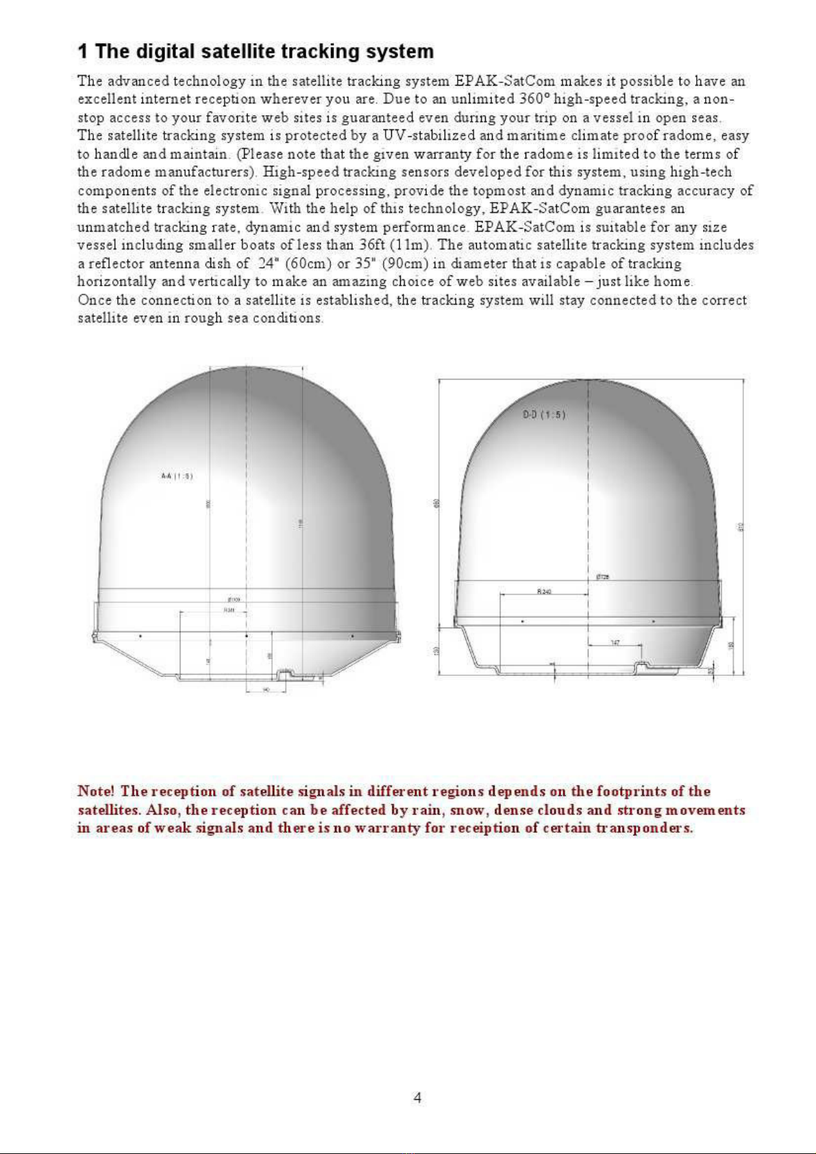
1 The digital satellite tracking system...................................................................................................4
1.1 EPAK®-SatCom s stem overview................................................................................................5
1.2 Safet recommendations................................................................................................................6
2 Installation............................................................................................................................................7
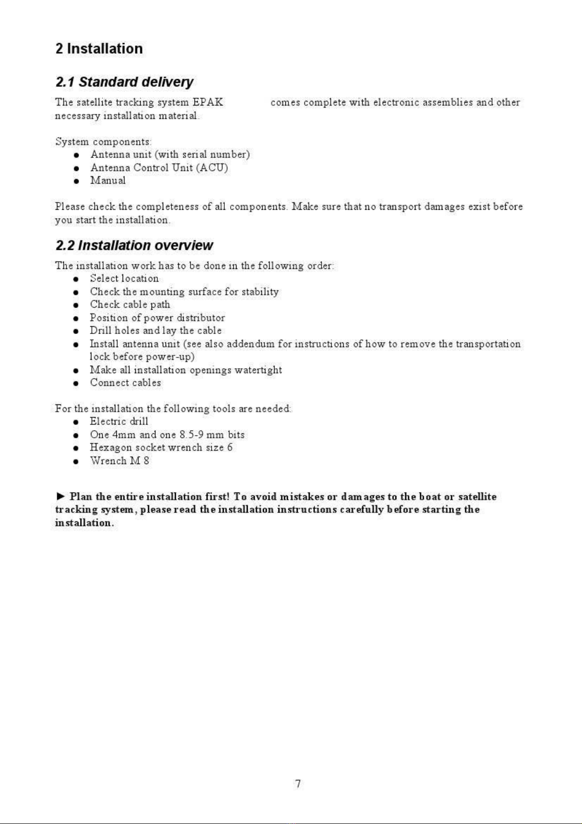
2.1 Standard deliver ............................................................................................................................7
2.2 Installation overview......................................................................................................................7
2.3 Selecting location...........................................................................................................................8
2.4 Mounting surface............................................................................................................................9
2.5 Planning the cable paths.................................................................................................................9
2.6 Power suppl ..................................................................................................................................9
2.7 Drillings..........................................................................................................................................9
2.8 Mounting the antenna unit............................................................................................................12
2.9 S stem cable connections.............................................................................................................12
Control elements.................................................................................................................................14
3.1 ACU..............................................................................................................................................14
3.2 Preparing the network behind the ACU.......................................................................................14
4 Operation............................................................................................................................................15
4.1 Menu tree......................................................................................................................................15
4.2 Preset............................................................................................................................................16
APPENDICES.......................................................................................................................................17
A Maintenance.......................................................................................................................................17
B Troubleshooting.................................................................................................................................18
C Technical specifications....................................................................................................................20
3
'6L
'6L
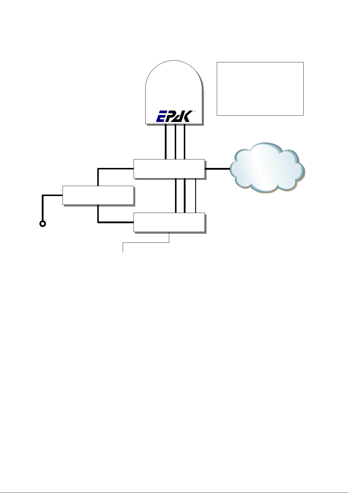
1.1 EPAK®-SatCom system overview
5
Antenna
Cable types:
RX,TX: double shielded coax cable
(RG6 type) with F-plugs
Ant: 2 x 2,5 ²
AC: Power cords (included)
LAN: Twisted Pair with RJ45 plugs
230V AC ACU
Ant RX TX
Mode
230V AC
LAN
RX TX
LAN
UPS
230V AC
GPS Input via NMEA
provided by ship
LAN
LAN
WAN

1.2 Safety recommendations
➔When mounting the antenna, the distance from the antenna unit to other radiation sources e.g.
radar equipment or other antennas (mobile communication antennas) should be minimum 3 m
(11 ft).
➔Simultaneous operation of radar and satellite antenna ma damage the satellite antenna if not
installed directl above the radar antenna.
➔Do not use the ACU unit outdoors.
➔During a thunderstorm, we recommend that the connection cables are disconnected.
➔If the negative side of the antenna unit’s suppl voltage has no connection to ship’s ground
(earth), then the antenna unit’s ground point should be connected directl to ship’s ground
(earth).
➔After the installation is completed, all other electronic s stems i.e. GPS, Radar, VHF, FM, AM
etc. should be tested for full functionalit , while the antenna is turned on.
➔Do not test or turn on the antenna before the radome is fitted correctl . If the sun reflects into
the dish, the electronics can be damaged.
➔Do not touch the rotar joint.
➔Do not attempt to open the sealed electronics, as this will void the warrant .
➔Do not sta closer than 5m to the antenna during operation
➔It is not allowed to use modem configurations with less than 153,6 kHz Tx Bandwidth
(@ - 3 dB)
6
'6L
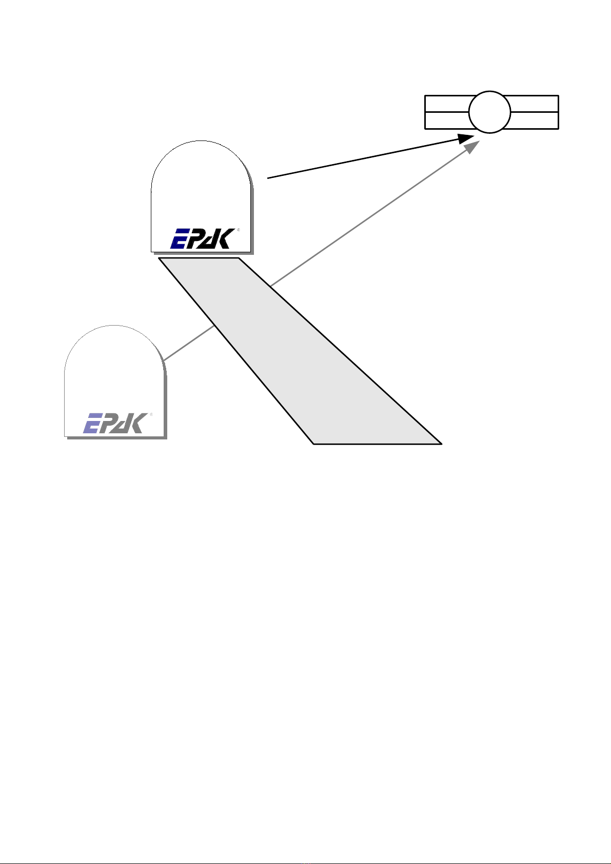
2.3 Selecting location
This illustration shows the importance of a proper location for the antenna unit.
Note that criteria such as an unobstructed view to the satellite and a strong mounting surface are met.
Furthermore, no sources of interference, e.g. radar equipment or other antennas, such as mobile
communication antennas, should be installed nearb the antenna unit.
Although the radome is sealed, it is recommended to avoid direct waves and bilge water!
The antenna unit has to be installed so that no superstructures will obstruct the sight to the satellite!
Please note, that the elevation angle depends on the geographical location of the boat and on the
selected satellite!
► Equally important for a good installation are the conditions of the mounting surface and the
lengths of the different cables. See section 2.4, 2.5 and 2.6.
8
Antenna
Antenna
Good view
Bad view
Satellite

2. Mounting surface
A horizontal, solid and stead surface is ver important. Make sure that the surface does not have an
irregularities! Furthermore, please take into consideration that the weight of the antenna unit is 56 kg
or more. Therefore, the surface has to be strong enough to carr the antenna unit, even during the most
challenging maritime conditions.
2.5 Planning the cable paths
Before starting the installation, ou should check which walls are suitable and if existing openings can
be used for the cables.
► All openings have to be sealed in order to avoid any water penetrating.
2.6 Power supply
The antenna unit is powered b the ACU using 24 V DC. The ACU is powered b a built in power
suppl , which is working on 230V AC. Max. power consumption is 150W. The circuit has to be fused
properl .
► The power distributor must be idle while working on the ship’s supply net or you may short
circuit the system.
If the chassis of the antenna unit has no connection to the boat's ground, make sure a potential
compensation between boat ground and the ground point of the antenna unit is made.
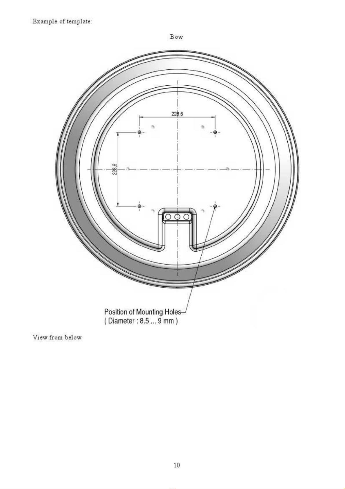
2.7 Drillings
To avoid an damage to the mounting surface it is recommended that ou start out with drilling a
smaller hole, using a 3.5-4 mm bit before drilling the correct hole size. Use an 8.5-9 mm bit to drill 4
mounting holes for the M8 screws included. To drill the holes in the correct positions, please refer to
the included template.
9
'6L
Questo manuale è adatto per i seguenti modelli
1
Indice
Altri manuali EPAK Antenna


Manuali Antenna popolari di altre marche

Alfa Network
Alfa Network APA-L01 Manuale utente

Naval
Naval PR-422CA Manuale utente

Feig Electronic
Feig Electronic ID ISC.ANTH200/200 Series Manuale utente

TERK Technologies
TERK Technologies TV44 Manuale utente

Directive Systems & Engineering
Directive Systems & Engineering DSE2324LYRMK Manuale utente

HP
HP J8999A Manuale utente


