ENGINEERING
PRODUCTS CO.
12-1-78
P.O. Box
1510
Waukesha,
Wisconsin
53187
48"
SNOWBLOWER FOR POWER KING
MODELS
1614,1618,
2414&
2418
PURPOSE
This
Snow
Blower
, manufactured by
Engineering
Products
Company and Haban
Manufacturing
Company
for
use on
the
Econ-
omy
tractor
, is intended
to
maintain
moderate areas
of
sidewalk,
driveway
and parking lot in
the
safe and
efficient
removal
of
light,
moderate and heavy
snow
cover.
Strict
adherence
to
the
assembly
and operating instructions
will
ensure
that
the
unit
will
have a
long and safe life.
ASSEMBLY
The
Snow
Blower
header is shipped
substantially
assembled
in one box and
the
hitch
in another. Finish assembling
the
unit
according
to
the
diagrams on pages 3, 4, and 5 and
the
following
instructions:
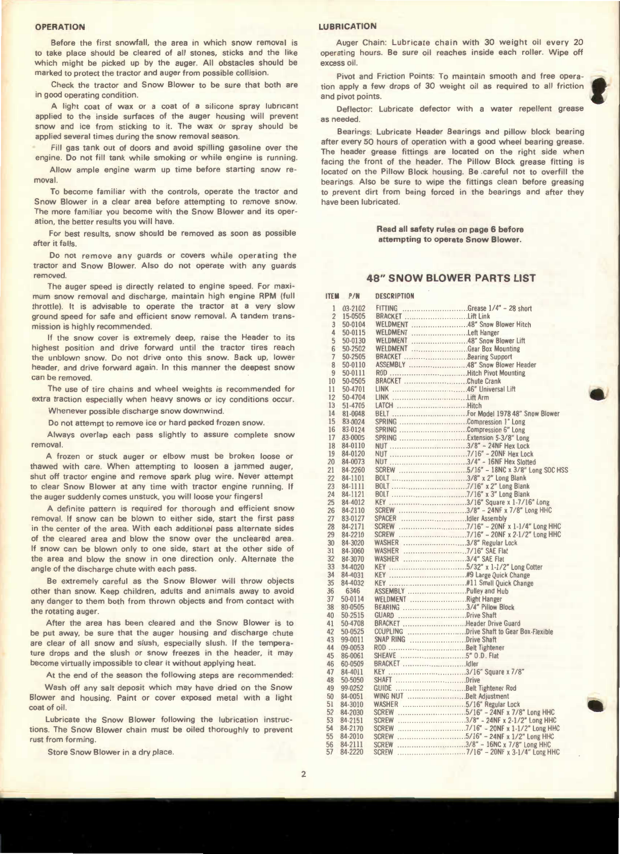
Bolt end
of
HITCH WELDMENT (Item 3) to
the
rear of
the
HEADER ASSEMBLY (Item
8)
using SCREW, 3/
8"
-24NF x 7/
8"
LONG HHC (Item 26) WASHER, 7/
16"
SAE FLAT (Item 31) and
NUT, 3/
8"
-24NF HEX LOCK (Item 18). Be sure
that
the
WASHERS
are over
the
slots
in
the
HEADER.
Bolt LIFT
ARM
LINK (Item 12) to HITCH
WELDMENT
(Item 3).
There are
two
holes on
this
end
of
the
LINK.
The
upper
hole
(marked
"D")
is
for
the
Power
King
1614
&
1618
models. The
lower
hole (marked
"C")
is
for
the
Power
King
2414
&
2418
models.
Run SCREW, 7/
16"
-20NF x 2-1 /
2"
LONG HHC (Item 29)
through
the
LINK,
then
through a WASHER, 7/
16"
SAE FLAT (Item 31)
through
the
tube welded
to
the
bottom
of
the
HITCH
WELDMENT
through
another
WASHER, (Item 31) and
into
NUT, 7/
16"
-20NF
HEX LOCK (Item 19). This
joint
must be free to turn.
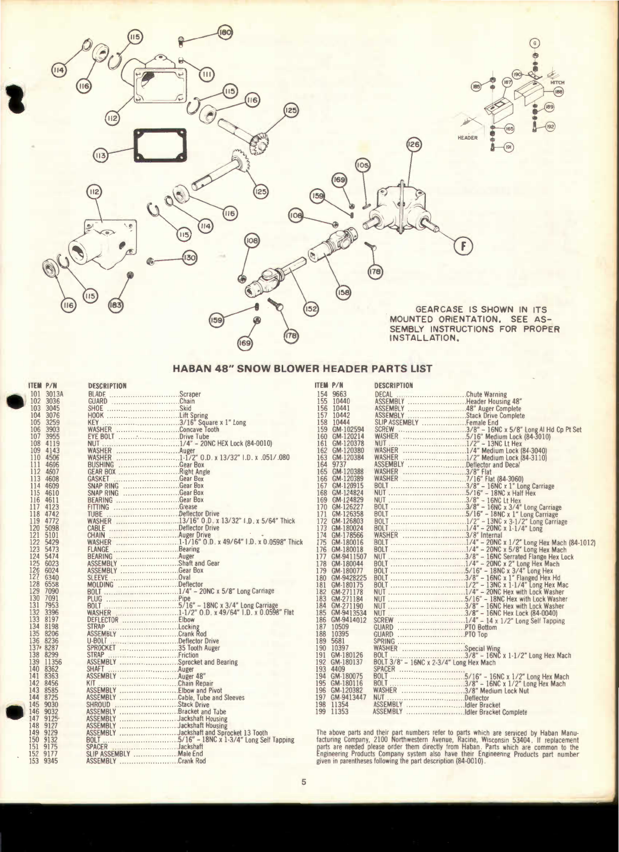
Slide female SLIP ASSEMBLY (Item
150)
into
male SLIP
AS-
SEMBLY (Item 152). Slide Sections
of
the
PTO
GUARDS (Items
187
and 188)
together
and
mount
to HEADER
flange
and
GUARD
BRACKET using
hardware
(Items
165, 185,
187
,
189,
190,
191,
192)
.
Assemble LIFT LINK (Item 11) as
shown
on page 3. It is very
important
that
the
KEYS (Item 34),
the
LIFT LINK BRACKET,
(Item 2),
the
SPRING (Item 16) and
the
WASHER (Item 32) be
in
the relative positions
shown
. This
arrangement
allows
the
HEADER
to
trip
up
when
a solid
object
is
struck and
therefore,
avoids
damage
to
the
HEADER, HITCH, and LIFT. The
length
of
the
LINK
is adjusted
for
the
various model
tractors
by placing
the
KEYS
and PINS in
the
appropriate locations. See
Diagram
on page 3.
Attach
the
LIFT LINK
to
lift
arm
on
Lift
Weldment
(Item 5) using
BOLT 7/
16"
x
2"
LONG BLANK (Item 23), SPRING (Item 15),
WASHER, 7/
16"
SAE FLAT (Item 31) and
KEY
#9
LARGE QUICK
CHANGE (Item 34).
Attach
the
CHUTE CRANK BRACKET (Item 1
0)
to
the
right
hand side
of
the
tractor
flywheel
housing.
Two
holes are provided
there
for
this
purpose. Use SCREW, 3/
8"
-24NF x 7/
8"
LONG
HHC (Item 26) and WASHER, 3/
8"
REGULAR LOCK (Item 30).
Place DISCHARGE CHUTE (Item 143) and DEFLECTOR
AS-
SEMBLY (Item 33)
through
the
DEFLECTOR DRIVE CABLE LOOP
(Item
120
and over
the
discharge stack on
the
HEADER.
Tighten
the
four BOLTS (Item
176)
at
the
DISCHARGE CHUTE base. These
BOLTS should
fit
under
the
ring on
the
HEADER
discharge
stack
to prevent
the
DISCHARGE CHUTE
from
coming
off
during
opera-
tion, yet
allow
it
to
rotate freely. Place both
interlocking
loops
of
the CABLE over
the
stud on
the
DISCHARGE CHUTE and
retain
with
WASHER, (Item 1
06)
and BOLT, 1I
4"
-20NC x 1/
2"
LONG
HEX
MACH
(Item
175)
.
The
Snow
Blower
is
now
fully
assembled and ready
for
mount-
ing,
final
adjustments
and operation.
MOUNTING
Mount
Snow
Blower
as
follows
:
Be sure
tractor
is on a level surface, is
not
running
and is
in
neutral. Place HEADER and HITCH ASSEMBLY
in
front
of
tractor
with
LIFT LINK extending
forward
toward
the
rear. Roll
the
tractor
forward
until HITCH PIVOT ROD is
just
slightly
ahead
of
tractor
rear
hitch
blocks. Leave
tractor
in
neutral
and
lift
rear of HITCH
and roll
tractor
forward
until
PIVOT ROD is in slot
in
rear
hitch
block. Tractor is
most
easily moved by
turning
tire,
either
front
or rear. Raise LIFT WELDMENT
until
bar
is
in
slot
of
tractor
front
hitch
block. Rotate HITCH LATCH
into
pos1t1on
and
retain
with
BOLT 3/
8"
x
2"
LONG BLANK (Item 22) and
KEY
, #11 ,
SMALL
QUICK CHANGE (Item 35).
Attach
rear end of LIFT LINK
to
tractor
lift
arm
using BOLT
7/
16"
x
3"
LONG BLANK (Item 24), SPRING (Item 15), WASHER
(Item 31) and
KEY
(Item 34). LIFT LINK should have already been
assembled
to
proper
length
referencing
the
diagram
on page 3.
Disconnect
the
Electromagnetic Clutch
wires
and
retaining
chain. Place BELT (Item 14) over clutch and
into
front
groove.
Reconnect
chain
and
wires.
It is desireable
to
wrap
the
wires
once
around
the
chain
when
reconnecting
to
avoid its rubbing on
the
engine screen and BELT
during
operation
.
Run BELT
down
around DRIVE SHAFT SHEAVE and around
IDLER SHEAVE.
Adjust
BELT
tension
by
turning
WING NUT so
that
about
1"
of
thread
shows
on BELT TENSIONING ROD. The
BELT
will
stretch
after
operation
begins
and
will
have
to
be re-
adjusted. Stop
engine
before making any adjustments.
Hook end of CRANK ROD (Item
135)
through
the
EYEBOLT
(Item 107) of chute
turning
assembly.
Slide
other
CRANK
ROD
(Item 107)
through
CHUTE CRANK (Item 10) and
into
the
end of
the
other
CRANK ROD.
ADJUSTMENTS
Adjust
SKID SHOES (Item 1
03)
to
the
desired
height
by block-
ing up
the
HEADER, loosening
the
BOLT (Item
131)
and NUT (Item
183), adjusting
Shoe
height, and
retightening
BOLT and NUT.
Adjust
both SHOES
to
the
same level.
If
operation
is
to
take place
on a gravel or stone
driveway
, etc
.,
it is recommended
that
the
SHOES
be
as
low
as possible. Both
the
SCRAPER BLADE (Item
101) and
the
SKID SHOES are subject
to
wear
and are designed
for easy replacement. Replace before
wear
is excessive
to
pre-
vent damage
to
the
auger housing.
A correctly adjusted AUGER CHAIN (Item
121)
will
have a
slight
amount
of
slack.
Adjust
this
CHAIN by loosening NUTS
(Item 161) at
the
HEADER end of
the
universal shaft, loosen
the
JAM
NUT (Item
168)
and
turn
BOLT (Item
150)
to
adjust CHAIN
tension. Clockwise
to
increase
tension,
counter-clockwise
to
decrease tension.
Re-tighten
JAM
NUT and NUTS (Item 161 ).
Check CHAIN periodically
to
maintain
proper
adjustment
. Do
not
run CHAIN
either
too
tight
or
too loose.
The DISCHARGE CHUTE CRANK is located on
the
right
hand
side of
the
tractor
. Turn CRANK to
control
the
direction
of
the
snow
discharge. The CHUTE rotates
thru
a
total
of
about
270°
and
should turn equally
far
in
either
direction
. Overtravel is
prohibited
by a chute stop bolt.
If
the
CHUTE travel is
not
the
same
in
both
directions, check
the
wrap
of
the
CABLE (Item
120)
and
the
TUBE
(Item 118). It should be
wrapped
2-1 / 2
times
around
the
TUBE
in
each direction.
If
the
DISCHARGE CHUTE
will
not
hold
in
a set
position,
tighten
the
NUT (Item 184)
until
the
CHUTE does
hold
its
position. Do
not
overtighten
.
The DEFLECTOR (Item 133) mounted on top
of
the
DISCHARGE
CHUTE
determines
the
distance
snow
is
thrown
.
Moving
the
top
of
the
DEFLECTOR
down
decreases
the
distance
while
raising
the
DEFLECTOR increases it.
/'),.SHUT
OFF
ENGINE
WHENEVER
ANY
ADJUSTMENTS/'),.
·
..
TO
THE
SNOW
BLOWER
ARE
MADE!
..