Epcom S04 Guida utente

POWERED BY
SERIESSERIES
Quick Operation Guide
UD.7L0202B1365B01
POWERED BY

POWERED BY
2
SERIESSERIES
Thank you for purchasing our product. If there is any question or request, please do not hesitate to contact dealer.
This manual is applicable to
S04, S08, S16
DVR Pre-Installation
The DVR is highly advanced surveillance equipment that should be installed with care. Please take
into consideration the following precautionary steps before installation of the DVR.
1. Keep all liquids away from the DVR.
2. Install the DVR in a well-ventilated and dust-free area.
3. Ensure environmental conditions meet factory specifications.
4. Install a manufacturer recommended HDD.
DVR Installation
During the installation of the DVR:
1. Use brackets for rack mounting.
2. Ensure there is ample room for audio and video cables.
3. When installing cables, ensure that the bend radius of the cables are no less than five times
than its diameter.
4. Allow at least 2cm (≈0.75-inch) of space between racks mounted devices.
5. Ensure the DVR is grounded.
6. Environmental temperature should be within the range of -10ºC ~ 55ºC, 14ºF ~ 131ºF.
7. Environmental humidity should be within the range of 10% ~ 90%.
Hard Disk Installation
Before you start:
Before installing a hard disk drive (HDD), please make surethe power is disconnected from the
DVR. A factoryrecommended HDD should be used for this installation.
Tools Required: Screwdriver.
To install a HDD on your DVR:
1. Remove the cover from theDVR by unfastening the screws on the back and
side.
2. Install the HDD in the HDD rack using the provided screws. Fasten the screws on the
bottom to fix the HDD.
3. Connect the HDD to the motherboard of the DVR with the included data cable, and
connect the power cable to the HDD.

POWERED BY
3
SERIESSERIES
4. Re-install the cover of the DVR and fasten screws.
Front Panel
S Series DVR
S Series DVR
Table 1Description of Indicators
Icon Description
1 Indicator turns red when DVR is powered up.
2Indicator lights in red when data is being read from or
written to HDD.
3Indicator blinks blue when network connection is
functioning properly.

POWERED BY
4
SERIESSERIES
Table 2 Description of Control Panel Buttons
Rear Panel
S Series DVR
The rear panel of S08 is shown below:
.
Table 3Description of Rear Panel

POWERED BY
5
SERIESSERIES
No. Item Description
1VIDEO IN BNC connector for analog video input.
2VIDEO
OUT
BNC connector for video output.
3
HDMI
HDMI video output.
4
VGA
DB15 connector for VGA output. Display local video
output and menu.
5AUDIO IN RCA connector for audio input.
6AUDIO
OUT
RCA connector for audio output.
7LAN
Interface
RJ45 10M / 100M Ethernet interface.
8
USB
Interface
Connects USB mouse or USB flash memory devices.
912V 12VDC power supply.
10
GND
Ground(needs to be connected when DVR starts up)

POWERED BY
6
SERIESSERIES
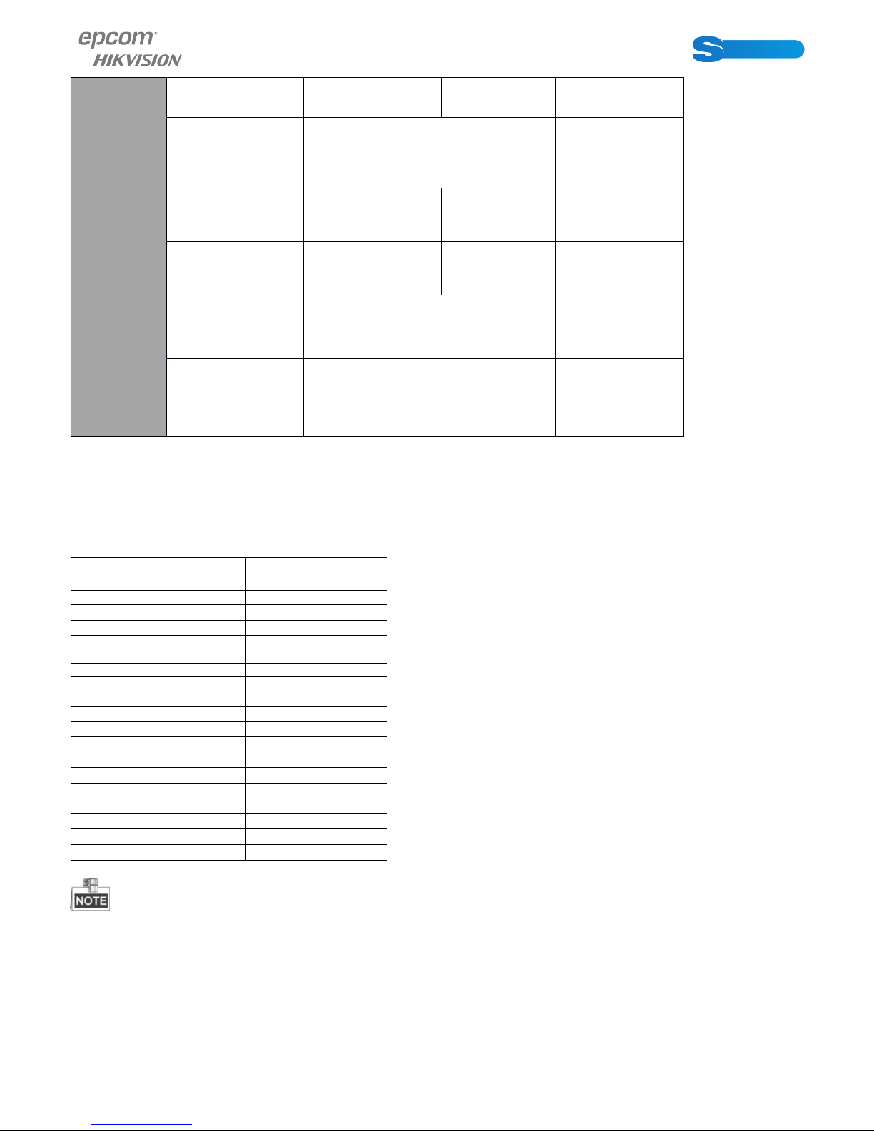
Specifications
Table 1 Specifications for S Series DVR
Model S 04 S 08 S 16
Video/
Audio
input
Video
compression H.264
Video input 4-ch 8-ch 16-ch
Video input
interface
BNC (1.0 Vp-
p, 75 Ω), PAL
/NTSC self-
adaptive
Audio
compression G.711u
Audio input 1-ch, RCA (2.0
Vp-p, 1 kΩ)
Two-way audio
input
1-ch, RCA (2.0
Vp-p, 1 kΩ)
(using the audio
input)

POWERED BY
7
SERIESSERIES
Video/
Audio
output
HDMI/VGA
output
1-ch,
resolution:
1080P:
CVBS output
1-ch, BNC (1.0
Vp-p, 75 Ω),
resolution: PAL:
704 × 576,
NTSC: 704 ×
480
Encoding
resolution
Frame rate 25 fps (P) / 30
fps (N)
Video bitrate
32 Kbps ~ 3072
Kbps, or user
defined (Max.
3072 Kbps)
Audio output 1-ch, RCA
(Linear, 1 kΩ)
Audio bitrate 64 Kbps
Dual-stream
Support;
Sub-stream:
CIF/QCIF @ 25
fps (P) / 30 fps
(N)
Stream type Video, Video &
Audio
Synchronous
playback 4-ch 8-ch 16-ch
Hard disk
SATA 1 SATA
interface
Capacity Up to 4TB
capacity
External
interface
Network
interface
1, RJ45 10M /
100M Ethernet
interface
USB interface 2, USB 2.0
POWERED BY
8
SERIESSERIES
General
Power supply 12 VDC
Consumption
(without hard
disk)
≤ 6 W ≤ 8 W ≤ 10 W
Working
temperature -10 ºC ~+55 ºC
Working
humidity 10% ~ 90%
Dimensions
(W × D × H)
200 × 200 ×
45 mm
200 × 200 ×
45 mm
285 × 210 ×
45 mm
Weight
(without hard
disk)
≤ 0.8 kg ≤ 1 kg ≤ 1.5 kg
HDD Storage Calculation Chart
The following chart shows an estimation of storage space used based on recording at one channel
for an hour at a fixed bit rate.
Bit Rate Storage Used
96Kbps 42M
128Kbps 56M
160Kbps 70M
192Kbps 84M
224Kbps 98M
256Kbps 112M
320Kbps 140M
384Kbps 168M
448Kbps 196M
512Kbps 225M
640Kbps 281M
768Kbps 337M
896Kbps 393M
1024Kbps 450M
1280Kbps 562M
1536Kbps 675M
1792Kbps 787M
2048Kbps 900M
3072Kbps 1350M
Please note that supplied values for storage space used is just for reference. Storage space
used is estimated by formulas and may have some deviation from actual value.
POWERED BY
9
SERIESSERIES
Menu Operation
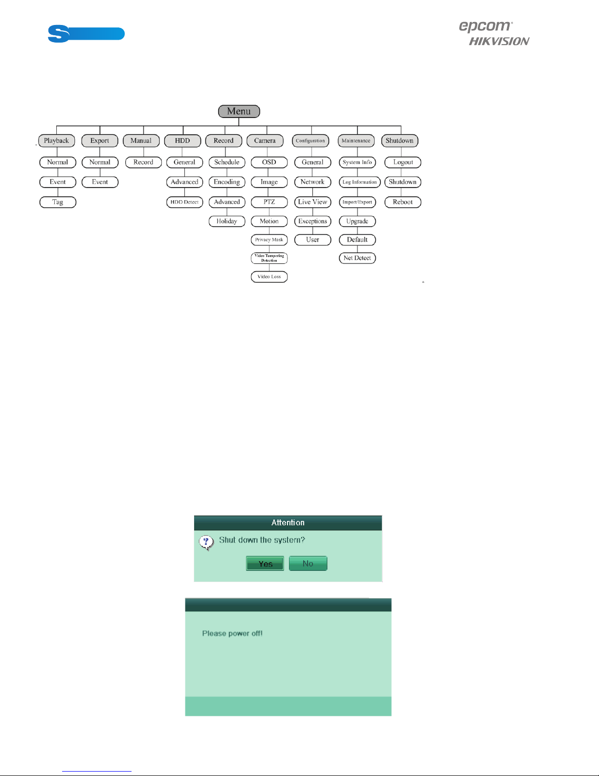
Menu Structure
The menu structureof the S series DVR isshown as below:
Startup and Shutdown
Proper startup and shutdown procedures are crucial to expanding the life of the DVR.
Before you start:
Check that the voltage of the extra power supply is the same with the device’s requirement, and
the ground connection is working properly.
Starting up the device:
Steps:
Check thepower supply is plugged into an electrical outlet. It is HIGHLY recommended that an
Uninterruptible Power Supply (UPS) be used in conjunction with the device. The Power indicator
LED should turn red indicating that the unit begins to start up.
Shuttingdown the device:
Steps:
1. Enter the Shutdown menu.
Menu >Shutdown
2. Click the Shutdown button to enter the following dialog box:
3. Click the Yes button. The following message box pops up:
Click the Yes button. The following message box pops up:

POWERED BY
10
SERIESSERIES
4. Disconnect the power supply of the device.
Using the Setup Wizard
The Setup Wizard can walk you through some important settings of thedevice.By default, the
Setup Wizard starts once the device has loaded.
Operating the Setup Wizard:
You can set the system language after the device is started. Click Apply to save the language
settings.
1. Check the checkbox to enable Setup Wizard when device starts. Click Next to continue the
setup wizard.
You can also click Cancel to exit the Setup Wizard, or use the Setup Wizard next time by
leaving the “Start wizard when device starts?” checkbox checked and exit.
2. ClickNextbutton on the Wizard window to enter the Loginwindow.
1) Enter the admin password. By default, the password is 12345.
2) To change the admin password, check the New Admin Password checkbox. Enter the new
password and confirm the password in the given fields.
Questo manuale è adatto per i seguenti modelli
2
Indice
Altri manuali Epcom Registratore digitale


