ePropulsion NAVY Tiller Handle Manuale utente

NAVY TILLER HANDLE USER MANUAL
Nov, 2018 Version 1.0
Copyright © 2018 ePropulsion All Rights Reserved


1
Acknowledgement
Thanks for choosing ePropulsion products, your trust and support in our
company are sincerely appreciated. We are dedicated to providing high-
performance electric outboards, as well as thrusters, reliable lithium batteries
and accessories.
Welcome to visit www.epropulsion.com and contact us if you have any
concerns.
Using This Manual
Before use of the product, please read this user manual thoroughly to
understand the correct and safe operations. By using this product, you
hereby agree that you have fully read and understood all contents of this
manual. ePropulsion accepts no liability for any damage or injury caused by
operations that contradict this manual.
Due to ongoing optimization of our products, ePropulsion reserves the rights
of constantly adjusting the contents described in the manual. ePropulsion
also reserves the intellectual property rights and industrial property rights
including copyrights, patents, logos and designs, etc.
This manual is subject to update without prior notice, please visit our website
www.epropulsion.com for the latest version. If you find any discrepancy
between your products and this manual, or should you have any doubts
concerning the product or the manual, please visit www.epropulsion.com.
ePropulsion reserves the rights of nal interpretation of this manual.
This manual is multilingual, in case of any discrepancy in the interpretation
of different language versions, the English version shall prevail.
Symbols
The following symbols will help to acquire some key information.
Important instructions or warnings
Useful information or tips

2
Product Identication
Below picture indicates the serial numbers of NAVY Tiller Handle. Please
note the position of the serial numbers and record them for access to
warranty service and other after-sale services.
Figure 0 -1
Model: NAVY Tiller Handle
Serial No.: DNTHXXXXXXX

3
Table of Contents
Acknowledgement .................................................................................... 1
Using This Manual...................................................................................... 1
Symbols ...................................................................................................... 1
Product Identication ................................................................................ 2
Table of Contents ....................................................................................... 3
1 Product Overview.................................................................................... 4
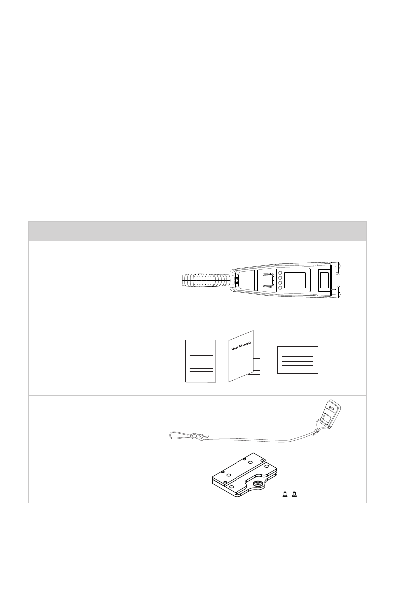
1.1 In the Package .................................................................................. 4
1.2 Parts and Diagrams .......................................................................... 5
1.3 Specication...................................................................................... 5
2 Mounting the Tiller Handle.................................................................... 6
3 Displaying...............................................................................................7
4 Charging............................................................................................... 11
4.1 Charging by solar power................................................................... 11
4.2 Charging by wired connection.......................................................... 11
5 Power Adjusting................................................................................... 13
5.1 Power Adjusting for Tiller Handle ..................................................... 13
5.2 Adjusting Maximum Forward/Backward Power ............................... 14
5.3 Recalibration .................................................................................... 15
6 Use of Kill Switch................................................................................. 17
7 Pairing Tiller Handle to the Outboard ............................................... 18
8 Warning Messages .............................................................................. 21
9 Warranty ................................................................................................ 24
9.1 Warranty Policies ............................................................................ 24
9.2 Out of Warranty............................................................................... 25
9.3 Warranty Claim Procedures ............................................................ 25

4
1 Product Overview
The NAVY Tiller Handle is used for starting and stopping the NAVY outboard
motor, adjusting the speed of the motor, conguring the battery parameters,
displaying the system information and messages, etc. The Tiller Handle is
powered by either solar power or the built-in lithium battery. Tiller Handle
wirelessly or wiredly communicates with the outboard control system built in
the main outboard motor.
1.1 In the Package
When you receive a set of NAVY Tiller Handle, unpack its package and
check if all the items below are included in the package. If there is any loss
or transport damage, please contact your dealer immediately.
Items Qty./Unit Figure
NAVY
Tiller Handle 1 set
User Manual,
Warranty
Card &
Invitation
Card
1 set
Kill Switch 2 pieces
Tiller Handle
Holder 1 set
Warranty
Invitation Card

5
1.2 Parts and Diagrams
Figure 1-1
1.3 Specication
NAVY Tiller Handle
Communication Wireless / Wired
Communication Distance ≤10 m
Weight 1.5 kg / 3.3 lbs.
Dimension (L x W x H) 574 mm x 120 mm x 100 mm /
22.6" x 4.7" x 4"
Throttle Handle
Buttons
Display Panel
Kill Switch
Communication Port
(Bottom)
Solar Panel
Forward/Reverse Icon Release Button

6
2 Mounting the Tiller Handle
Before using the Tiller Handle, users should mount it to the outboard motor
by one simple step:
Align the Tiller Handle to the mounting recess of the outboard motor in the
direction of the arrow and plug in the Tiller Handle until a click sound is
heard.
Figure 2-1
If it is the first time to mount the Tiller Handle to the outboard, it is
necessary to install the tiller handle holder on the outboard (Figure 2-2)
before mounting the Tiller Handle.
Figure 2-2
To detach the Tiller Handle: press the release buttons (Figure 2-3) on both
sides of the Tiller Handle and plug it out.
Figure 2-3
Release Button
Tiller Handle Holder
M8 Screw
Not to jam the outboard cable
while mounting the tiller.

7
3 Displaying
Battery Level Indicator
Throttle Reset Indicator
Battery Level/Voltage
Kill Switch Status Indicator
Overheat Alert
Current Speed
Distance/Time
Throttle Power
GPS Status Indicator
Travelled Distance/
Time or Remaining
Distance/Time
Figure 3-1
Buttons Functions
“Power”
1. In power-off state, press and hold the power button to power
on the Tiller Handle.
2. In power-on state, press and hold the power button to power
off the Tiller Handle.
“OK”
1. On setting pages, press " " button to save the current
settings and switch to the next item.
2. On setting pages, press and hold “ ” button, and the
system will save your settings, the display will exit from
setting page and return to the home page.
3. In power-on state, when home page displays or all the
characters display on the page, press “ ” button
and hold 5s to enter the Tiller Handle pairing page.

8
Buttons Functions
^
“Up”
1. On any setting page, press “
^
” button to view options for
current setting.
2. In power-on state, when home page displays, press “
^
”
button and hold 10s to enter the throttle calibration page.
3. On home page, press “
^
” button to switch the travelling
distance or time displaying icon between “ ” and “ ”.
press
“Up”
button
Main page 1 Main page 2
“Menu”
1. In power-on state, press and hold “ ” button to enter the
preference setting page.
Preference setting page
2. On preference setting page, press and hold “ ” button to
enter the battery setting page.
Battery setting page
3. On any page, press “ ” button to return home page.
Indice


