Esse-ti GSM500 Manuale utente

7IS-80395 06/03/2020
User’s manual

TABLE OF CONTENTS
GENERAL INSTALLATION INSTRUCTIONS .............................. 4
General Notes ................................................................................. 4
Making the installation ................................................................... 4
DESCRIPTION .................................................................................. 5
Features .................................................................................................... 6
LED .......................................................................................................... 7
GSM500 hardware description ................................................................ 8
3G hardware description .......................................................................... 9
INSTALLATION ............................................................................. 10
Installation recommendations ................................................................ 10
EU declaration of conformity ................................................................ 10
Inserting the SIM card ........................................................................... 11
Inserting the antenna .............................................................................. 11
Connection to the telephone line ........................................................... 12
Connection to the power supply ............................................................ 12
Turning the gateway on ......................................................................... 13
Gateway mounting operations ............................................................... 14
GSM500 absorption chart ...................................................................... 15
3G absorption chart ................................................................................ 15
PROGRAMMING............................................................................ 16
Programming by telephone .......................................................... 16
(1) SIM card expiration check ................................................................. 21
(2) Battery check ...................................................................................... 22
(3) External power failure control............................................................ 22
(4) Relay-based notification of external power failure and/or mobile
network loss ........................................................................................... 23
(5) Automatic converter of selected telephone number........................... 23
Programming via SMS ................................................................. 26
Message format ...................................................................................... 26
Notification message format .................................................................. 28
SERVICES ....................................................................................... 30
Incoming calls .............................................................................. 30
Outgoing calls .............................................................................. 30
Measuring the signal level ........................................................... 31

Reading SIM card expiration ....................................................... 32
Reading the battery status ............................................................ 32
Activation relay ............................................................................ 33
SENDING SMS THROUGH DB-9 ................................................. 34
Sending received SMS text messages.................................................... 35
Sending SMS from device wired in the DB-9 connector ...................... 36
DATA TRANSMISSION ................................................................ 37
FEMALE DB-9 CONNECTOR ....................................................... 40
SIGNALS ......................................................................................... 41
Tones ............................................................................................ 41
Call signals ................................................................................... 42
LED .............................................................................................. 42
GSM/UMTS signal indicator LED (GREEN) ....................................... 42
Status indicator LED (RED) .................................................................. 43
Line status indicator LED / Data transmission indicator LED (WHITE)
................................................................................................................ 43
Power supply status indicator LED (BLUE) ......................................... 44
PROBLEM-DETECTION GUIDE .................................................. 45

Page 4
GENERAL INSTALLATION
INSTRUCTIONS
GENERAL NOTES
Carefully read the notes contained in this section as they provide important
information on safe correct installation, use and maintenance of the product.
The product must be EXCLUSIVELY used for the purpose it was designed for.
Esse-ti shall not be responsible for damages arising from improper use.
The product has been designed in compliance with the regulations in force and
must be installed in systems that comply with the provisions of law.
Always disconnect power supply before performing internal or external operations
on the product (cleaning, maintenance, etc.).
Always refer to an authorized service centre for repair.
The device must be installed in a ventilated place, making sure that the ventilation
slots are never obstructed.
Do not install the product in environments with risk of explosion.
Make sure that the product has been installed as required.
Do not introduce objects, liquids or powders inside the product. Do not use sprays
inside the product.
Packing components (such as plastic bags, foam polystyrene, etc.) must be kept out
of the reach of children because potentially dangerous.
MAKING THE INSTALLATION
Internal telephone installations must be carried out by specialised personnel.
The installation and connection of telephone terminals to the telecommunications
network that do not comply with the regulations in force is not permitted.

Page 5
DESCRIPTION
GSM500
GSM500 is a gateway that, connected to a fixed telephone or to the PSTN
input terminals of a PABX or autodialer, allows you to make and receive
calls over the GSM network. For correct operation, a GSM SIM card is
required.
GSM500 GC
The GSM500 GC gateway comes with built-in backup batteries.
GSM500 R2R
The GSM500 R2R gateway comes with built-in backup batteries and a
relay output which can be activated either locally or remotely via SMS.
GSM500.net
The GSM500.net gateway comes with built-in backup batteries and
female DB-9 connector for data transmission (through standard RS-
232/RS-485/CAN-bus) and SMS forwarding (through standard RS-
232/CAN-bus). For correct operation, a GSM (voice + data) SIM card is
required (GPRS data connection).
3G.next Voice
3G.next Voice is a gateway that, connected to a fixed telephone or to the
PSTN input terminals of a PABX or autodialer, allows you to make and
receive calls over the UMTS/GSM network. The 3G.next Voice gateway
comes with built-in backup batteries and a relay output which can be
activated either locally or remotely via SMS.
3G.next
The 3G.next gateway comes with a female DB-9 connector for data
transmission and SMS forwarding and a micro USB A/B port for direct
connection to the UMTS/GSM module (optional). For correct operation
the SIM card must be enabled for voice and data traffic.

Page 6
Features
Local programming via DTMF tones
Remote programming via SMS
Display of caller identification
Automatic country setting
CLIP / CLIR
Roaming setting
SIM card expiration check
Battery check (only available on models: GC, R2R, .net and 3G)
External power failure control (only available on models: GC, R2R,
.net and 3G)
Relay-based notification of external power failure (only available on
models: R2R and 3G)
Relay-based notification of GSM network loss (only available on
GSM500 R2R)
Relay-based notification of UMTS/GSM network loss (only
available on models: 3G)
SMS notifications (SIM card expiration, low-battery, dead battery,
replaced battery, external power failure/restore, GSM/UMTS
network restore)
Measurement of GSM/UMTS signal level
Automatic converter of selected telephone number
Receiver and transmitter gain adjustment
Remote reboot function
Data transmission through standard RS-232, RS-485 and CAN-bus
(only available on GSM500.net)
Data transmission through standard RS-232 and CAN-bus (optional
RS-485; only available on 3G.next)
Incoming text messages transmission towards devices wired in the
DB-9 connector under RS-232 standard (only available on
GSM500.net and 3G.next)

Page 7
Text messages transmission by devices wired into the DB-9
connector under RS-232 or CAN-bus standard (only available on
GSM500.net and 3G.next)
Remote firmware update
GSM/UMTS signal indicator LED
Status indicator LED
Line status indicator LED / Data transmission indicator LED (only
available on GSM500.net and 3G.next)
Power supply status indicator LED
Quad Band GSM module (GSM500 all versions)
Dual Band UMTS/GSM module (3G all versions)
2 W transmission power
12 Vdc power supply input
230 Vac external adapter input
Female DB-9 connector (only available on GSM500.net and 3G.next)
Micro USB A/B port (optional, only available on 3G.next)
Relay output (1 A, 24 V; only available on models: R2R and 3G)
External antenna (cable length = 2 m)
External adapter (230 Vac 50 Hz input; 12 Vdc 500 mA output; CE
mark; only available on models: GC, R2R, .net and 3G)
LED
The gateway is equipped with 4 outer LEDs.
LEDs flashing is described at chapter “SIGNALS” (see page 42).
Green LED: GSM/UMTS signal indicator LED
Red LED: Status indicator LED
/ White LED: Line status indicator LED / Data transmission
indicator LED (only available on GSM500.net and 3G.next)
Blue LED: Power supply status indicator LED
Page 8
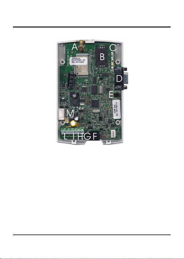
GSM500 hardware description
Remove the cover by pressing the upper side.
A ANTENNA cable connector
B SIM CARD housing with front panel
C LED indicating signal strength (green), LED indicating device operation status
(red), LED indicating line status / data transmission (white) and LED indicating
power supply status (blue)
D Female DB-9 connector (.net models only)
E Jumper (.net model only)
F Telephone line output (RJ11 connector) for telephone set connection or PABX
analogue line connection
G 230Vac external adapter input
H Telephone line output (terminal block) for connection of autodialer/PABX
analogue line
I 12Vdc power supply terminal block
L Relay terminal block (R2R model only)
M Backup battery connector (GC, R2R and .net models only)
Page 9
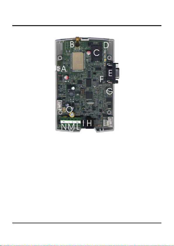
3G hardware description
Remove the cover by pressing the upper side.
A Micro USB A/B port (optional, 3G.next)
B ANTENNA cable connector
C SIM CARD housing with front panel
D LED indicating signal strength (green), LED indicating device operation status
(red), LED indicating line status / data transmission (white) and LED indicating
power supply status (blue)
E Female DB-9 connector (3G.next)
F RS-485 termination jumper (3G.next)
G CAN-bus termination jumper (3G.next)
H Telephone line output (RJ11 connector) for telephone set connection or
autodialer/PABX analogue line connection
I 230 Vac external adapter input
L Telephone line output (terminal block) for telephone set connection or
autodialer/PABX analogue line connection
M 12 Vdc power supply terminal block
N Relay terminal block
O Backup battery connector

Page 10
INSTALLATION
Installation recommendations
The gateway must be installed in a location where the radio signal
allows for using the GSM/UMTS system.
It is advisable to leave plenty of space around the gateway for
maintenance operations.
Do not install the gateway outdoors, since it lacks protection devices
against weather conditions that can damage the gateway (water,
humidity, etc.).
Do not install the gateway near electronic (radio or TV sets, Personal
Computers, wired radio systems, etc.) or magnetic (credit cards, floppy
disks, etc.) devices that could be subjected to RF interference from the
module: recommended distance from the antenna is min. 2,5 m.
Do not install the gateway near medical devices. Its operation may cause
damage to hearing aids or pacemakers.
Always make sure that the device operation is permitted in the place of
installation (e.g. installation is not allowed in hospitals, airplanes, etc.).
EU declaration of conformity
Hereby, Esse-ti S.r.l. declares that the equipment type GSM500/3G.next
is in compliance with Directive 2014/53/EU.
The full text of the EU declaration of conformity is available from the
following Internet address:
https://www.esse-ti.it/en/dichiarazioni-di-conformita
Altri manuali per GSM500
1
Indice
Altri manuali Esse-ti Portale


Manuali Portale popolari di altre marche

LST
LST M500RFE-AS Manuale utente

Kinnex
Kinnex Media Gateway Manuale utente

2N Telekomunikace
2N Telekomunikace 2N StarGate Manuale utente

Mitsubishi Heavy Industries
Mitsubishi Heavy Industries Superlink SC-WBGW256 Manuale utente

ZyXEL Communications
ZyXEL Communications ZYWALL2 ET 2WE Manuale utente

Telsey
Telsey CPVA 500 - SIP Manuale utente


