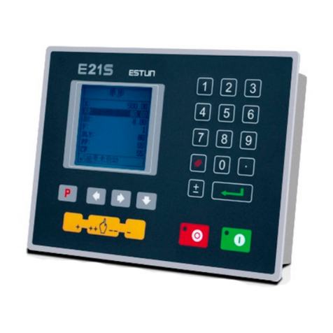
Estun E21 Manuale utente

Page 1 of 38
E21 Press Brake Numerical Control Device
Installation Manual
V1.01
ESTUN AUTOMATION CO.,LTD
Address :No.155 Jiangjun Road, Jiangning
Development Zone Nanjing P.R.C 211106
Postal code:211106
TEL:025-52785569
FAX:025-52785966
WEB:www.estun.com
E-mail:[email protected]

Page 2 of 38
Document Revision Record
Serial
No.
Version
No.
Revision
Date
Description Revised by Appr
oved
by
Remarks
1 V1.00 2012-6-4 Yao Qing
2 V1.01 2012-6-6 Update
Assembly
Drawings
Yao Qing

Page 3 of 38
Preface
Target reader
This manual is applicable to operators of E21 press brake machine numerical
control device, including:
Machine tool operators
Installation and maintenance personnel
Range of application
Installation and maintenance personnel can install and operate this device
properly by referring to this manual.
Regulation
The design of E21 press brake machine numerical control device complies
with the following grade standard:
Grade standard of EMC test:
1. GBT 17626.2-2006 Electromagnetic compatibility(EMC)- Testing and
measurement techniques - Electrostatic discharge immunity test.
Grade 3, contact discharge ±4KV,air discharge ±8KV.
2. GBT 17626.4-2008 Electromagnetic compatibility - Testing and
measurement techniques - Electrical fast transient/burst immunity test
Grade 3, power port ±2KV,communication port ±1KV.
3. GBT 17626.3-2006 Electromagnetic compatibility - Testing and
measurement techniques - Radiated radio-frequency electromagnetic
field immunity test
Grade strength:10V/m,criteria:Grade A.
4. GB/T 17626.8-2006 Electromagnetic compatibility(EMC) - Testing
and measurement techniques - Power frequency magnetic field immunity
test
30A/m,50~60HZ,criteria:Grade A.
5. RE Test,reference standard EN55011
Execute CLASS A standard.
Environmental test standard
6. Low temperature; refer to JB-T 8832-2001 General requirements for
numerical control systems of machine tools, 0 , 2hours. Low℃
temperature store -20 . Criteria: normal start up, normal operation.℃
7. High temperature, refer to JB-T 8832-2001 General requirements for
numerical control systems of machine tools, 40 , 2hours. High℃
temperature store 55 . Criteria: normal operation.℃
8. Constant temperature wet, refer to JB-T 8832-2001 General requirements
for

Page 4 of 38
numerical control systems of machine tools, 40 , humidity 93%~95%℃,
2 hours. Criteria: normal operation.
9. Vibration impact, refer to JB-T 8832-2001 General requirements for
numerical control systems of machine tools.
Personnel
Only authorized and properly trained person is allowed to operate this
equipment. Any person without necessary training is not allowed to use this
control system, not even for temporary use.
Area of responsibility distributed for personnel participating in installing,
operating and servicing equipment shall be stipulated explicitly and be
confirmed eligible.

Page 5 of 38
Content
Preface ..........................................................................................................................3
1 Specification.............................................................................................................7
1.1 Display ...................................................................................................................................7
1.2 Internal memory.....................................................................................................................7
1.3 Electrical specification...........................................................................................................7
1.4 Encoder specification.............................................................................................................8
2 Installation ...............................................................................................................9
2.1 Annoucements before installation ..........................................................................................9
2.2 Installation space and direction..............................................................................................9
2.3 Installation environment ........................................................................................................9
2.4 Installation dimension..........................................................................................................10
2.5 Installation layout.................................................................................................................10
2.5.1 Layout of rear panel....................................................................................................10
2.5.2 Rear panel port description ......................................................................................... 11
2.5.3 Overall wiring scheme ................................................................................................12
2.5.4 Electrical wiring scheme.............................................................................................12
2.6 Definition of system interface..............................................................................................13
2.6.1 Definition of power interface......................................................................................13
2.6.2 Definition of input interface .......................................................................................13
2.6.3 Definition of external output interface........................................................................15
2.6.4 Definition of encoder interface ...................................................................................15
2.6.5 Definition of communication interface.......................................................................16
3 Parameter Description of Machine Tool ..........................................................17
3.1 Enter parameter page ...........................................................................................................17
3.2 Parameter specification ........................................................................................................18
4 Debugging..............................................................................................................22
4.1 Preparation before debugging ..............................................................................................22
4.2 Debugging procedure...........................................................................................................22
4.3 Debugging............................................................................................................................22
4.4 Actual processing .................................................................................................................24
5 Diagnosis ................................................................................................................25
5.1 Enter diagnosis page ............................................................................................................25
5.2 Input diagnosis.....................................................................................................................25
5.3 Output diagnosis ..................................................................................................................26
5.4 Keyboard diagnosis..............................................................................................................26
5.5 FRAM diagnosis ..................................................................................................................27
5.6 Encoder diagnosis ................................................................................................................28
5.7 LCD diagosis .......................................................................................................................28

Page 6 of 38
6 Maintenance...........................................................................................................29
6.1 Instructions to maintenance .................................................................................................29
6.2 Routine inspection ...............................................................................................................29
6.3 Periodic inspection...............................................................................................................30
7 Appendix ................................................................................................................32
7.1 External power description ..................................................................................................32
7.2 Grounding design.................................................................................................................32
7.2.1 Ground classification in equipment cabinet................................................................32
7.2.2 Equipment grounding design ......................................................................................33
7.3 Protective measures..............................................................................................................34
7.3.1 Measures to ensure electromagnetic compatibility .....................................................34
7.3.2 Instructions to E21 electricmagnetic compability installation ....................................36
7.3.3 Install freewheeling diode on relay.............................................................................36
7.4 Demonstration of AC Asynchronism motor wiring .............................................................36

Page 7 of 38
1 Specification
1.1 Display
LCD display
Dimension of display window:54.38mm*54.38mm
Dot matrix:160*160
Status light
Green indicates running;
Red indicates stop.
1.2 Internal memory
Capable of storing 40 programs, each program includes 25 steps at most.
1.3 Electrical specification
POWER
Input voltage:DC24V±10%
Rated current:1A
INPUT
Input voltage:DC24V±10%
Maximum input current:10mA
OUTPUT
External voltage:DC24V±10%
Maximum current:70mA

Page 8 of 38
Encoder power
Output voltage:DC12V±5%
Allowable maximum output current:500mA
Absolute temperature:
Working temperature:0~40℃
Storage temperature:-20~55℃
1.4 Encoder specification
Power supply is DC 12V;
Incremental encoder,single-ended output,with Z/C phase;
Voltage-type output

Page 9 of 38
2 Installation
2.1 Annoucements before installation
Power supply must be off during installation and wiring.
Serious damage to the equipment may be caused by misconnection of
power supply terminals, improper connection of in-out lines and output
line short circuit. Therefore, before turning on the power supply, check
the connection of input output grounding and power supply wire. .
Grounding terminal of E21 digital control device must be grounded in
correct way, with low impedance lower than 0.3Ω.
Do not dismantle the device without authorization so as to avoid
malfunction.
Electrical components inside the digital device are very sensitive to static
electricity, therefore do not put foreign matters or make them fall to the
inside of digital control device or touch the control circuit.
Please install E21 digital control device in safe region. Avoid high
temperature, and direct sunlight, moisture and splash of oil drops or
water.
Do not use this device in place of high temperature, moisture
condensation, dust, oil smoke, conductive dust, corrosive gas or
flammable gas.
2.2 Installation space and direction
Generally, E21 bending machine digital control device is embedded on control
panel, keep a distance of 65mm from its neighboring components and damper
(shell) on up and down, right and left, to facilitate operator install and
maintain the device.
2.3 Installation environment
Place free from water, vapor, dust or oily dust.
Place free from flammable, explosive or corrosive gas.
Place free from interference of strong electromagnetism or noise.
Ambient temperature is between 0℃- 40 . When ambient temperature is℃
over 40 , please put it in well℃-ventilated place.
Relative humidity is under 90%RH.

Page 10 of 38
2.4 Installation dimension
The installation method is panel-mounting. Installation dimension and
drawings are shown in Figure 2-1.
Figure 2-1 Panel Installation Dimension
2.5 Installation layout
2.5.1 Layout of rear panel
Rear panel block diagram is shown in Figure 2-2, consisting of power port
(POWER), input port (INPUT), output port (OUTPUT), encoder port (X, Y),
and communication port (COMM).
Altri manuali per E21
2
Indice
Altri manuali Estun Controllori

Estun
Estun TRIO Flex-X Nano Manuale utente

Estun
Estun E21 Manuale utente

Estun
Estun Trio MC404-Z Manuale utente

Estun
Estun E-Series Manuale utente

Estun
Estun E200P Manuale utente

Estun
Estun E21S Manuale utente

Estun
Estun S1E Series Manuale utente

Estun
Estun EP1000 PLC Manuale del proprietario

Estun
Estun E200 Guida utente

Estun
Estun TRIO Flex-6 Nano Manuale utente