EUROCOM L295U Series Manuale utente

L295U / L297U


Preface
I
Preface
LCD Computer
L295U/L297U Series
Service Manual

Preface
II
Preface
Notice
The company reserves the right to revise this publication or to change its contents without notice. Information contained
herein is for reference only and does not constitute a commitment on the part of the manufacturer or any subsequent ven-
dor. They assume no responsibility or liability for any errors or inaccuracies that may appear in this publication nor are
they in anyway responsible for any loss or damage resulting from the use (or misuse) of this publication.
This publication and any accompanying software may not, in whole or in part, be reproduced, translated, transmitted or
reduced to any machine readable form without prior consent from the vendor, manufacturer or creators of this publica-
tion, except for copies kept by the user for backup purposes.
Brand and product names mentioned in this publication may or may not be copyrights and/or registered trademarks of
their respective companies. They are mentioned for identification purposes only and are not intended as an endorsement
of that product or its manufacturer.
Version 1.0
September 2004
Trademarks
Intel®, Pentium® and Celeron® are US registered trademarks of Intel Corporation.
Windows®is a registered trademark of Microsoft Corporation.
Other brand and product names are trademarks and/or registered trademarks of their respective companies.

Preface
III
Preface
About this Manual
This manual is intended for service personnel who have completed sufficient training to undertake the maintenance and
inspection of personal computers.
It is organized to allow you to look up basic information for servicing and/or upgrading components of the computer.
The following information is included:
Chapter 1, Introduction, provides general information about the location of system elements and their specifications.
Chapter 2, Disassembly, provides step-by-step instructions for disassembling parts and subsystems and how to upgrade
elements of the system.
Appendix A, Part Lists
Appendix B, Schematic Diagrams

Preface
IV
Preface
Related Documents
You may also need to consult the following manual for additional information:
User’s Manual on CD
This describes the computer’s features and the procedures for operating the computer and its ROM-based setup program.
It also describes the installation and operation of the utility programs provided with the computer.

Preface
V
Preface
Contents
Introduction ..............................................1-1
Overview .........................................................................................1-1
Model Differences ...........................................................................1-2
System Specifications L295U/L297U .............................................1-3
External Locator - Front View ........................................................1-6
External Location - Left & Right Side Views .................................1-7
External Locator - Rear View .........................................................1-8
Mainboard Overview - Top .............................................................1-9
Key Parts .........................................................................................1-9
Mainboard Overview - Bottom .....................................................1-10
Key Parts .......................................................................................1-10
Mainboard Overview - Top ...........................................................1-11
Cable Connectors and Switches ....................................................1-11
Mainboard Overview - Bottom .....................................................1-12
Cable Connectors and Switches ....................................................1-12
Disassembly ...............................................2-1
Overview .........................................................................................2-1
Maintenance Tools ..........................................................................2-2
Connections .....................................................................................2-2
Maintenance Precautions .................................................................2-3
Disassembly Steps ...........................................................................2-4
Removing the Hard Disk Drive Assembly ......................................2-5
Removing the LCD Back Cover .....................................................2-6
Removing the System Memory .......................................................2-7
Removing the CPU ..........................................................................2-8
Removing the I/O Bracket .............................................................2-10
Removing the Modem ...................................................................2-11
Removing the Floppy Disk Drive Assembly ................................2-12
Removing the Mini PCI I/F Module .............................................2-13
Removing the CD Device Assembly (L295U Series) .................. 2-14
Removing the CD Device Assembly (L297U Series) .................. 2-15
Part Lists ..................................................A-1
Part List Illustration Location ........................................................ A-2
L295U - Base ................................................................................. A-3
L295U - Back ................................................................................ A-4
L295U - Front ................................................................................ A-5
L295U - Card Reader Module ....................................................... A-6
L295U - Combo ............................................................................. A-7
L295U - Toshiba DVD .................................................................. A-8
L295U - FDD ................................................................................. A-9
L295U - HDD .............................................................................. A-10
L297U - Base ............................................................................... A-11
L297U - Back .............................................................................. A-12
L297U - Front .............................................................................. A-13
L297U - Card Reader Module ..................................................... A-14
L297U - CD-ROM ....................................................................... A-15
L297U - Combo ........................................................................... A-16
L297U - Toshiba DVD-RW ........................................................ A-17
L297U - FDD ............................................................................... A-18
L297U - HDD .............................................................................. A-19
L297U - Video Capture Card Module ......................................... A-20
Schematic Diagrams.................................B-1
System Block Diagram ...................................................................B-2
Northwood - 1 of 2 .........................................................................B-3
Northwood - 2 of 2 .........................................................................B-4
Clock Generator ..............................................................................B-5
MCH Power ....................................................................................B-6
MCH Host .......................................................................................B-7

Preface
VI
Preface
MCH AGP ...................................................................................... B-8
MCH Memory ................................................................................B-9
MCH Memory Termination ......................................................... B-10
DDR RIMM .................................................................................B-11
DVO Chrontel CH7107A .............................................................B-12
LCD Connector ............................................................................ B-13
CRT & USB ................................................................................. B-14
ICH5 (Power, LPC, Clock, SMbus) ............................................. B-15
ICH5 (PCI, IDE, UHB, USB, LAN) ............................................B-16
Thermal & Fan Controller ............................................................B-17
Cardbus PCI1520 .........................................................................B-18
IEEE 1394 .................................................................................... B-19
Cardbus Slot & Mini PCI .............................................................B-20
LAN RTL8100BL ........................................................................B-21
IDE Connector & Firmware Hub .................................................B-22
SIO W83627HF ............................................................................B-23
Serial & Parallel Port ....................................................................B-24
CODEC ........................................................................................B-25
Amplifiers & Inverter Connector .................................................B-26
Power 1 .........................................................................................B-27
Power 2 .........................................................................................B-28
Power 3 .........................................................................................B-29

Introduction
Overview 1 - 1
1.Introduction
1: Introduction
Overview
This manual covers the information you need to service or upgrade the L295U/L297U LCD computer. Information about
operating the computer (e.g. getting started, and the Setup utility) is in the User’s Manual. Information about drivers (e.g.
VGA & audio) is also found in User’s Manual. That manual is shipped with the computer.
Operating systems (e.g. DOS, Windows 9x, Windows NT 4.0, Windows 2000, Windows XP, OS/2 Warp, UNIX, etc.) have
their own manuals as do application software (e.g. word processing and database programs). If you have questions about
those programs, you should consult those manuals.
The L295U/L297U LCD computer is designed to be upgradeable. See “Disassembly” on page 2 - 1 for a detailed de-
scription of the upgrade procedures for each specific component. Please note the warning and safety information indi-
cated by the “” symbol.
The balance of this chapter reviews the computer’s technical specifications and features.
Introduction
1 - 2 Model Differences
1.Introduction
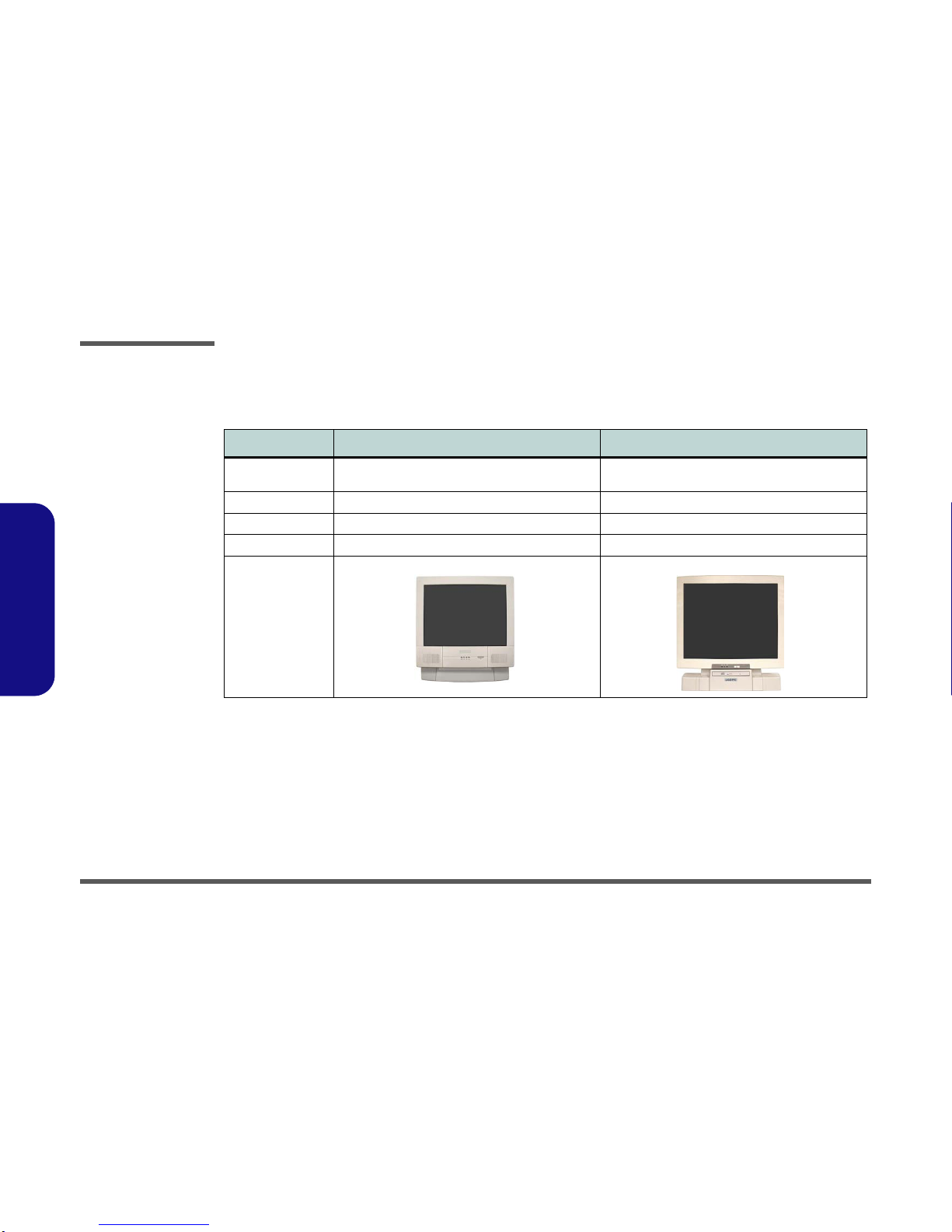
Model Differences
The differences between the model types are indicated in the table and pictures below.
Feature/Model L295U Series L297U Series
LCD Size Color TFT 15" XGA LCD Panel (supporting a resolution
of 1024*768 256K colors) Color TFT 17" SXGA LCD Panel (supporting a
resolution of 1280*1024 16 million colors)
CD Device Location Left Side Front
Dimensions 369mm (H) * 384mm (W) * 188mm (D 395mm (H) * 418mm (W) * 179mm (D)
Weight 8.9 Kg 10.2 Kg
Designs Supported
(Additional Colors
Also supported)
Table 1 - 1
Model
Specifications
Questo manuale è adatto per i seguenti modelli
1
Indice
Altri manuali EUROCOM Scrivania

EUROCOM
EUROCOM UNO 2.1 Manuale utente

EUROCOM
EUROCOM L295P B Manuale utente

EUROCOM
EUROCOM T890M Manuale utente

EUROCOM
EUROCOM Multimedia PC V12.1.00 Manuale utente

EUROCOM
EUROCOM LP200ST Manuale utente

EUROCOM
EUROCOM LCD PC Manuale utente

EUROCOM
EUROCOM A110SU Manuale utente

EUROCOM
EUROCOM LCD PC Manuale utente

EUROCOM
EUROCOM LP295 Manuale utente

EUROCOM
EUROCOM LP295UB Manuale utente


