Evco EVXS815 Guida utente

Evco S.p.A. EVSX815 | Installer manual ver. 1.2 | Code 144XS815E124
page 1 of 58
EVXS815
Split execution controller for
temperature-controlled blast chillers
(integrated into the unit)
ENGLISH
INSTALLER MANUAL ver. 1.2
CODE 144XS815E124

Evco S.p.A. EVSX815 | Installer manual ver. 1.2 | Code 144XS815E124
page 2 of 58
Important
Important
Read this document thoroughly before installation and before use of the device and follow all recommendations; keep
this document with the device for future consultation.
The following symbols support reading of the document:
indicates a suggestion
indicates a warning
The device must be disposed of in compliance with local Standards regarding the collection of electric and electronic
equipment.

Evco S.p.A. EVSX815 | Installer manual ver. 1.2 | Code 144XS815E124
page 3 of 58
Index
1INTRODUCTION ................................................................................................................................. 5
1.1 Introduction....................................................................................................................................... 5
1.2 Summary table of the main features and the models available ................................................................. 6
2DESCRIPTION .................................................................................................................................... 9
2.1 Description of the user interface........................................................................................................... 9
2.2 Description of the control module ....................................................................................................... 10
3DIMENSIONS AND INSTALLATION ...................................................................................................... 11
3.1 User interface dimensions.................................................................................................................. 11
3.2 Control module dimensions................................................................................................................ 11
3.3 User interface installation .................................................................................................................. 12
3.4 Control module installation ................................................................................................................ 12
3.5 Installation warnings ........................................................................................................................ 12
4ELECTRIC CONNECTION.................................................................................................................... 13
4.1 Electric connection............................................................................................................................ 13
4.1.1 Connection of the terminating resistors....................................................................................... 14
4.2 Warnings for the electric connection ................................................................................................... 14
5USER INTERFACE ............................................................................................................................. 15
5.1 Foreword......................................................................................................................................... 15
5.2 Switching the device on/off................................................................................................................ 15
5.3 The display...................................................................................................................................... 15
5.4 Cabinet temperature display .............................................................................................................. 15
5.5 Display of the temperature detected by the needle probe ...................................................................... 16
5.6 Evaporator temperature display ......................................................................................................... 16
5.7 Defrosting activation in manual mode ................................................................................................. 16
5.8 Switch-on/off of the cabinet light in manual mode ................................................................................ 16
5.9 Locking/unlocking the keyboard ......................................................................................................... 17
5.10 Silencing the buzzer ..................................................................................................................... 17
6OPERATION ..................................................................................................................................... 18
6.1 Foreword......................................................................................................................................... 18
6.2 Blast chilling and storage................................................................................................................... 18
6.3 Hard blast chilling and storage ........................................................................................................... 19
6.4 Deep freezing and storage................................................................................................................. 21
6.5 Soft deep freezing and storage........................................................................................................... 22
6.6 Pre-cooling start-up.......................................................................................................................... 23
6.7 Management of the test regarding correct insertion of the needle probe .................................................. 23
6.8 Switching on UV light for sterilisation cycle .......................................................................................... 24
6.9 Heating the needle probe .................................................................................................................. 24
7“HACCP” FUNCTION.......................................................................................................................... 25
7.1 Foreword......................................................................................................................................... 25
7.2 Display of information relative to the HACCP alarms .............................................................................25
7.3 Deleting the information relative to the HACCP alarms .......................................................................... 26
8COMPRESSOR OPERATING HOURS COUNT .......................................................................................... 27
8.1 Display of compressor operating hours................................................................................................ 27
8.2 Deleting the compressor operating hours ............................................................................................ 27
9CONFIGURATION.............................................................................................................................. 28
9.1 Setting the real date and time............................................................................................................ 28
9.2 Setting the configuration parameters .................................................................................................. 28

Evco S.p.A. EVSX815 | Installer manual ver. 1.2 | Code 144XS815E124
page 4 of 58
9.3 Restoring the factory settings ............................................................................................................ 29
9.4 List of configuration parameters ......................................................................................................... 29
10 SIGNALS AND INDICATIONS.............................................................................................................. 40
10.1 Signals ....................................................................................................................................... 40
10.2 Indications .................................................................................................................................. 42
11 ALARMS .......................................................................................................................................... 43
11.1 Alarms........................................................................................................................................ 43
12 ERRORS .......................................................................................................................................... 45
12.1 Errors ......................................................................................................................................... 45
13 ACCESSORIES ................................................................................................................................. 47
13.1 EVKEY programming key............................................................................................................... 47
13.1.1 Introduction ............................................................................................................................ 47
13.1.2 Description.............................................................................................................................. 47
13.1.3 Dimensions ............................................................................................................................. 48
13.1.4 Uploading the configuration parameters...................................................................................... 48
13.1.5 Downloading the configuration parameters.................................................................................. 48
13.2 Non-optoisolated RS-485/TTL serial interface EVIF20TSX .................................................................. 49
13.2.1 Introduction ............................................................................................................................ 49
13.2.2 Description.............................................................................................................................. 49
13.2.3 Dimensions ............................................................................................................................. 49
13.2.4 Connection to the device........................................................................................................... 49
13.3 EVPROG01 connection kit .............................................................................................................. 50
13.3.1 Introduction ............................................................................................................................ 50
13.3.2 Description.............................................................................................................................. 50
13.3.3 Dimensions ............................................................................................................................. 51
13.3.4 Connection to the device........................................................................................................... 52
13.4 Polyster adesive ovelay 0041600277 ..............................................................................................52
13.4.1 Introduction ............................................................................................................................ 52
13.4.2 Description.............................................................................................................................. 52
13.5 Technical data ............................................................................................................................. 53

Evco S.p.A. EVSX815 | Installer manual ver. 1.2 | Code 144XS815E124
page 5 of 58
1INTRODUCTION
1.1 Introduction
EVXS815 is a digital controller studied to manage temperature-controlled blast chillers, which can be mechanically and
aesthetically integrated into the unit.
The controller is fitted with:
- clock
- signal buzzer and alarm
- 3 analogue inputs (cabinet probe, needle probe and evaporator probe) for PTC/NTC probes
- 2 digital inputs (door micro switch and high pressure)
- 5 digital outputs (electromechanical relays), 1 x 30 A res. @ 250 VAC for compressor management, 2 x 16 A
res. @ 250 VAC for management or defrosting and a utility set for door heating elements or the condenser fan,
2 x 8 A res. @ 250 VAC for management of the evaporator fan and a fifth utility that can be set for the cabinet
light, needle probe heating or UV light; defrosting can be electric, hot air, air or air with door open
- serial port with MODBUS communication protocol.
The device can manage both temperature and timed blast chilling and storage cycles and deep freezing and storage
cycles and also the hard and soft types.
Every operating cycle can be preceded by pre-cooling; the temperature-controlled cycles are also preceded by a two-
stage test for verification of the correct insertion of the needle probe.
The device is available in “split” execution (user interface + control module).
The user interface is look in open frame board and is made up from a custom 4 digit display (with function icons) and
6 touch-keys; installation is envisioned by back panel via M3 studs.
The control module is without cover and installation is envisioned on flat surface with spacers.
Via the "HACCP" function, up to 9 events can be memorised for each of the 3 HACCP alarms (temperature-controlled
blast chilling or deep freezing not concluded within the maximum duration alarm, maximum temperature during
storage alarm and power cut during storage alarm); the critical value, date and time at which the alarm occurred and
the duration can be memorised for each HACCP alarm.
The configuration parameters can be uploaded and downloaded using the EVKEY programming key (to be ordered
separately).
Via a serial interface (to be ordered separately), it is also possible to connect the controller to the Parameters Manager
set-up software system, to the monitoring and surveillance system of the RICS plants or to the data recording device,
to download the recorded data (via USB), to upload and download EVUSBREC01 configuration parameters.
The following are indicated among the many other features:
- direct loads connection (except the utility managed by the fifth digital output)
- management of three types of backlight
- memorisation of the defrosting interval
- management of temperature alarms
- compressor operating hours count
- "keyboard lock" function.

Evco S.p.A. EVSX815 | Installer manual ver. 1.2 | Code 144XS815E124
page 6 of 58
1.2 Summary table of the main features and the models
available
The following table illustrates the main features of the device and the models available.
“ / “ indicates the feature can be set via a configuration parameter.
User interface (without cover) EVXS815
156.0 x 45.0 mm (6.141 x 1.771 in; L x H) •
custom 4 digit display (with function icon) •
number of keys 6
°C decimal point •
Control module (without cover) EVXS815
99.0 x 108.0 mm (3.897 x 10.798 cm; L x H) •
Connections EVXS815
faston + fixed screw terminal board •
Power supply EVXS815
115... 230 VAC •
Analogue inputs EVXS815
cabinet probe PTC/NTC
needle probe PTC/NTC
evaporator probe PTC/NTC
Digital inputs (for NO/NC contact) EVXS815
door micro switch •
high pressure •
Digital outputs (electromechanical relays; A res. @
250 VAC) EVXS815
compressor 30 A
defrosting 16 A

Evco S.p.A. EVSX815 | Installer manual ver. 1.2 | Code 144XS815E124
page 7 of 58
evaporator fan 8 A
door heating elements/condenser fan 16 A
cabinet light/needle probe heating/UV light 8 A
Communication port EVXS815
serial port with MODBUS communication protocol •
Other features EVXS815
clock •
signal buzzer and alarm •
direct loads connection except for the utility managed by the fifth digital output
management of three types of backlight •
management of blast chilling and storage/deep freezing
and storage cycles •
management of temperature/time controlled operation
cycles •
hard/soft operating cycles management •
management of the test regarding correct insertion of
the needle probe •
memorisation of the defrosting interval •
management of temperature alarms •
compressor operating hours count •
“HACCP” function •
"keyboard lock" function •
configuration parameters access password •
restoring the factory settings •
Codes EVXS815
codes EVXS815P9

Evco S.p.A. EVSX815 | Installer manual ver. 1.2 | Code 144XS815E124
page 8 of 58
For further information, see chapter 14 "TECHNICAL DATA"; for other models contact the Evco sales network.

Evco S.p.A. EVSX815 | Installer manual ver. 1.2 | Code 144XS815E124
page 9 of 58
2DESCRIPTION
2.1 Description of the user interface
The following drawing illustrates the aspect of the EVXS815 user interface.
The following table illustrates the meaning of EVXS815 user interface parts.
Part Meaning
1 display
2 blast chilling key
3 defrosting/auxiliary key, hereon also called “DEEP FREEZING key”
4 hard blast chilling or soft deep freezing key, hereon called HARD/SOFT" key
5 communication port with the control module (signal)
6 switch-on/switch-off/cycle start/cycle cut-off key, hereon called "START/STOP key"
7 increase key, hereon call "UP key"
8 decrease key, hereon call "DOWN key"
For further information, see the next chapters.

Evco S.p.A. EVSX815 | Installer manual ver. 1.2 | Code 144XS815E124
page 10 of 58
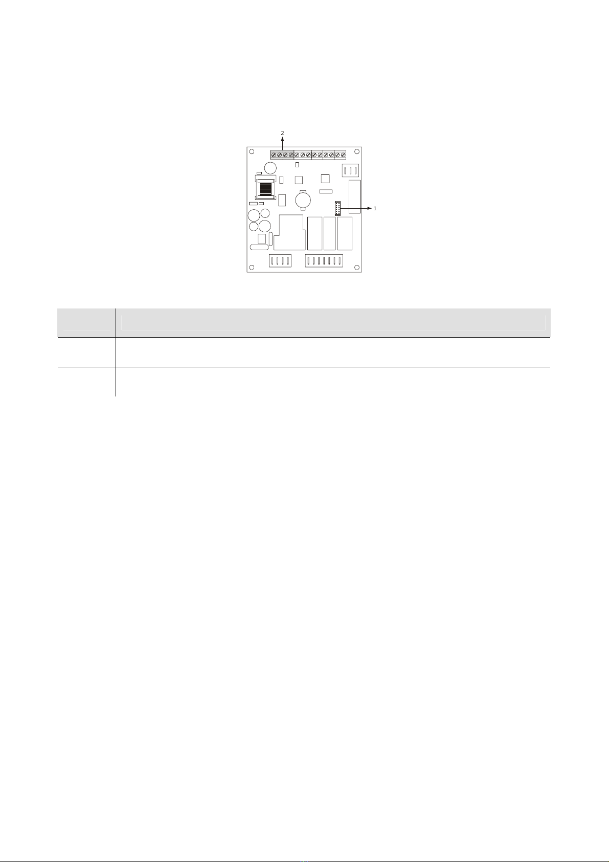
2.2 Description of the control module
The following drawing illustrates the aspect of the EVXS815 control module.
The following table illustrates the meaning of EVXS815 control module parts.
Part Meaning
1 serial port with MODBUS communication protocol
2 communication port with the user interface (signal and power supply)
For further information, see the next chapters.
Indice
Altri manuali Evco Controllori

Evco
Evco EV8318 Manuale utente

Evco
Evco c-pro 3 OEM Manuale utente

Evco
Evco EV3143 Manuale utente

Evco
Evco EV3 MVC Series Istruzioni per l’uso

Evco
Evco C-PRO NANO Manuale utente

Evco
Evco EVD MVC Series Manuale utente

Evco
Evco Vcolor 869 Guida utente

Evco
Evco c-pro 3 nano CHILL Manuale utente

Evco
Evco EV3C23 Manuale utente

Evco
Evco EV3S204 Manuale utente

Evco
Evco EVF215 Manuale utente

Evco
Evco C-PRO NANO Series Manuale utente

Evco
Evco Vcolor 579 Guida utente

Evco
Evco C-pro 3 giga Manuale utente

Evco
Evco c-pro 3 nano Series Manuale utente

Evco
Evco Vcolor 679 Guida utente

Evco
Evco EVF214 Manuale utente

Evco
Evco EVJ Basic Split Manuale utente

Evco
Evco EVJ 200 Manuale utente

Evco
Evco c-pro 3 OEM HRV Guida utente