Evco Vcolor 388 Guida utente

EVCO S.p.A. Vcolor 388 | Installer manual ver. 1.0 | Code 144VC388E104
Page 1 of 44
Vcolor 388
Controllers for steam tube deck ovens
ENGLISH
INSTALLER ANUAL ver. 1.0
CODE 144VC388E104

EVCO S.p.A. Vcolor 388 | Installer manual ver. 1.0 | Code 144VC388E104
Page of 44
Important
Read this document carefully before installation and before
using the device and take all the prescribed precautions. Keep
this document with the device for future consultation.
Only use the device in the ways described in this document. Do
not use the device as a safety device.
Disposal
The device must be disposed of according to local regulations
governing the collection of electrical and electronic equipment.

EVCO S.p.A. Vcolor 388 | Installer manual ver. 1.0 | Code 144VC388E104
Page 3 of 44
Contents
1 INTRODUCTION .................................. 4
1.1 Product description ............................. 4
1. Models available and technical features . 5
MEASUREMENTS AND INSTALLATION.... 8
.1 Format features .................................. 8
. Control module measurements and
installation ......................................... 8
.3 User interface measurements ............... 8
.4 User interface installation .................. 10
.5 Installation precautions ..................... 10
3 ELECTRICAL CONNECTION ................. 11
3.1 Vcolor 388M electrical connection ....... 11
3. Vcolor 388L electrical connection ........ 1
3.3 Precautions for electrical connection ... 13
4 FIRST-TIME USE ............................... 13
4.1 First-time use .................................. 13
5 OPERATION ..................................... 14
5.1 Initial information ............................. 14
5. Locked display ................................. 14
5.3 Splash screen .................................. 14
5.4 Stand-by screen ............................... 14
5.5 Configuration screen ......................... 15
5.6 Delayed start screen ......................... 16
5.7 Home screen .................................... 18
5.8 Change chamber setpoint screen ........ 19
5.9 Cycle settings/start-up screen ............ 19
6 MANAGING LOADS ........................... 4
6.1 Initial information ............................. 4
6. Burner ............................................ 4
6.3 Chimney damper for combustion fume
extraction ........................................ 4
6.4 Suction hood .................................... 4
6.5 Chamber light .................................. 4
6.6 Steam injection ................................ 4
6.7 Venting ........................................... 5
6.8 Buzzer ............................................ 5
6.9 Sound ............................................. 5
6.10 Electronics compartment fan .............. 5
6.11 Fan motor ........................................ 5
6.1 Type 1 or burner block reset ........... 5
7 LIST OF CONFIGURATION
PARAMETERS ................................... 6
8 ALARM MANAGEMENT ....................... 31
9 CONNECTIVITY ................................. 34
9.1 Initial information ............................. 34
9. EPoCA cloud platform ........................ 35
10 USING THE USB PORT ....................... 36
10.1 Initial information ............................. 36
10. Uploading the recipe settings ............. 36
10.3 Downloading the recipe settings ......... 36
10.4 Uploading the settings in the configuration
parameters ...................................... 36
10.5 Downloading the settings in the
configuration parameters ................... 36
10.6 Uploading CSV files to personalise the
graphics, recipes and languages ......... 36
11 ACCESSORIES .................................. 37
11.1 relay expansion ............................. 37
11. Safety transformer ............................ 37
11.3 Non-optoisolated RS-485/USB serial
interface .......................................... 37
11.4 USB plug for panel installation ............ 37
11.5 Connecting cables ............................. 37
11.6 Buzzer expansion.............................. 38
11.7 4GB USB flash drive .......................... 38
11.8 EVlinking Wi-Fi RS-485 module .......... 38
11.9 EV3 Web gateway ............................. 38
1 TECHNICAL SPECIFICATIONS ............. 39
1 .1 Technical data .................................. 39

EVCO S.p.A. Vcolor 388 | Installer manual ver. 1.0 | Code 144VC388E104
Page 4 of 44
1INTRODUCTION
1.1 Product description
Vcolor 388 is a controller for steam tube deck ovens which have a centralised gas burner heating system. The controller has an open
frame board and a remote user interface which consists of a 5-inch (M) or 7-inch (L) capacitive TFT touch-screen graphic display in glass
which is installed vertically, either semi-recessed into the front or flush with the panel. It has 15 outputs with electro-mechanical relays
(which can be expanded to 19 by fitting up to optional modules in the dedicated slots on the main board) and can control from 3 to 5
decks: management of temperature and extraction of combustion and cooking fumes is centralised, whereas cycle duration, steam
injection and venting are controlled separately for each deck.
The controller can save up to 99 recipes, each of which can be selected for any deck. Every recipe can have up to 8 phases, each with
independent settings for duration, steam injection and venting. Recipes can be altered, overwritten and saved directly from the display
and two different oven pre-heating setpoints can be set for every day of the week, with two start/stop times scheduled for each setpoint.
Recipes can be compiled in an ODS file (complete with pictures in BMP or GIF format) and uploaded to the controller using a USB flash
drive, thanks to the innovative programmable platform which allows users to customise their recipes and add new languages.
The controller has an oven cleaning function which uses pyrolysis, a self-cleaning mechanism that does not require chemical detergents
as food residue is oxidised at high temperature.
Users can interact remotely with their equipment and start up/stop working cycles using the EPoCA® cloud platform with Wi-Fi or Ethernet
connectivity (which also enables alternative or parallel control through MODBUS TCP). For more details, compare all the connectivity
options in the Technical Data table and consult the Management and Monitoring Products/Systems and the Connectivity Products/Devices
sections of our website.

EVCO S.p.A. Vcolor 388 | Installer manual ver. 1.0 | Code 144VC388E104
Page 5 of 44
1.2 odels available and technical features
The table below shows the technical features of the models available.
Vcolor 388 & L
Optional expansion
modules with 2
relays (max. 2)
with J/K
thermocouples
with Pt 100
2 wires
odule
1
odule
2
Power supply
Control module 1 Vac 1 Vac
User interface Powered by the
control module
Powered by the
control module
Expansion modules Powered by the
control module
Analogue inputs (J/K or Pt100)
Chamber probe J/K thermocouples Pt 100 wires
Digital inputs for NO/NC contact (voltage-free)
Safety thermostat for combustion and cooking chamber fumes
(connected in series) • •
Chimney adjustment rod • •
Motorised chimney damper • •
Burner door • •
Digital inputs for NO/NC contact (high voltage 230 Vac)
Burner block • •
Fan block • •
Digital outputs (electro-mechanical relays; A res. @ 250
Vac)
Configurable K1 (default burner) 5 A 5 A
Configurable K (default burner block) 5 A 5 A
Configurable K3 (default combustion fume extraction) 5 A 5 A
Configurable K4 (default steam injection deck 5) 5 A 5 A
Configurable K5 (default chamber light) 5 A 5 A
Configurable K6 (default suction hood) 5 A 5 A
Configurable K7 (default electronics compartment fan) 5 A 5 A

EVCO S.p.A. Vcolor 388 | Installer manual ver. 1.0 | Code 144VC388E104
Page 6 of 44
Configurable K8 (default sound) 5 A 5 A
Configurable K9 (default burner power supply) 8 A 8 A
Configurable K10 (default steam injection deck 1) 5 A 5 A
Configurable K11 (default steam injection deck ) 5 A 5 A
Configurable K1 (default steam injection deck 3) 5 A 5 A
Configurable K13 (default steam injection deck 4) 5 A 5 A
Configurable K14 (default fan motor) 5 A 5 A
Configurable K15 (default venting deck 1) 5 A 5 A
Configurable K16 (default venting deck ) 5 A
Configurable K17 (default venting deck 3) 5 A
Configurable K18 (default venting deck 4) 5 A
Configurable K19 (default venting deck 5) 5 A
Communications ports
RS-485 MODBUS • •
USB • •
Connectivity
RS-485 MODBUS RTU (built-in) • •
Wi-Fi EPoCA/MODBUS TCP (optional through the EVlinking Wi-Fi
module powered by controller) • •
Ethernet EPoCA/MODBUS TCP (optional through EV3 Web
gateway) • •
Other features
Clock • •
Alarm buzzer • •
Functions
Cooking timer for every deck • •
99 recipes • •
Pre-heating delayed start • •
For more information, see section 1 “TECHNICAL SPECIFICATIONS”.
The table below lists the purchasing codes of the available models:

EVCO S.p.A. Vcolor 388 | Installer manual ver. 1.0 | Code 144VC388E104
Page 7 of 44
Purchasing codes
Vcolor 388 with J/K thermocouples
Vcolor 388 (control module + 5” user interface kit):
EVC C38FJ2E (flush fit installation from behind)
EVC C38FJ2EF (semi-recessed installation into the front)
Vcolor 388 L (control module + 7” user interface kit):
EVCLC38FJ2E (flush fit installation from behind)
EVCLC37FJ2EF (semi-recessed installation into the front)
Vcolor 388 with Pt 100 2 wires
Vcolor 388 (control module + 5” user interface kit):
EVC C38FC2E (flush fit installation from behind)
EVC C38FC2EF (semi-recessed installation into the front)
Vcolor 388 L (control module + 7” user interface kit):
EVCLC38FC2E (flush fit installation from behind)
EVCLC38FC2EF (semi-recessed installation into the front)
Optional
EVCLE322XXE: expansion module with relays (maximum modules)
EVIF25SWX: EVlinking Wi-Fi module
EV3W01: IoT EV3 Web gateway
For more models, contact the EVCO sales network.

EVCO S.p.A. Vcolor 388 | Installer manual ver. 1.0 | Code 144VC388E104
Page 8 of 44
2EASURE ENTS AND INSTALLATION
2.1 Format features
The control module is available in a split version with an open frame board. User interfaces are available in 5 or 7-inch versions for vertical
operation and have capacitive colour TFT touch-screen graphic displays.
2.2 Control module measurements and installation
Measurements are expressed in mm (inches). Installation is on a flat surface with spacers.
2.3 User interface measurements
The user interface is available in the model which is installed flush and the model which is semi-recessed into the front. The measurements
vary according to the model, as illustrated below in mm (in).
Vcolor 388

EVCO S.p.A. Vcolor 388 | Installer manual ver. 1.0 | Code 144VC388E104
Page 9 of 44
Vcolor 388L

EVCO S.p.A. Vcolor 388 | Installer manual ver. 1.0 | Code 144VC388E104
Page 10 of 44
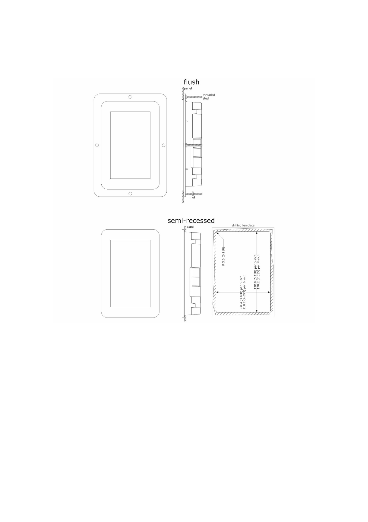
2.4 User interface installation
Depending on the model, installation can be:
-flush, from behind the panel with threaded studs (not provided) welded to hold it in place;
-semi-recessed, from the front of the panel with spring clips to hold it in place.
2.5 Installation precautions
- ensure that the working conditions for the device (operating temperature, humidity, etc.) are within the set limits. See section
1 “TECHNICAL SPECIFICATIONS”
- do not install the device close to heat sources (heaters, hot air ducts, etc.), equipment with a strong magnetic field (large
diffusers, etc.), in places subject to direct sunlight, rain, damp, excessive dust, mechanical vibrations or shocks
- any metal parts close to the control module must be far enough away so as not to compromise the safety distance
- in compliance with safety regulations, the device must be installed properly to ensure adequate protection from contact with
electrical parts. All protective parts must be fixed in such a way as to need the aid of a tool to remove them
- ensure that the thermocouple is properly insulated from contact with metal parts or use already insulated thermocouples.
Questo manuale è adatto per i seguenti modelli
10
Indice
Altri manuali Evco Controllori

Evco
Evco EVJS 800 Series Guida utente

Evco
Evco EVK614 Manuale utente

Evco
Evco EV3 700 Series Manuale utente

Evco
Evco EVX225 Manuale utente

Evco
Evco EVBOX Light JS200 Manuale utente

Evco
Evco EV3H94 Manuale utente

Evco
Evco EVXS815 Guida utente

Evco
Evco EVJ 700 Guida utente

Evco
Evco EVJ 200 Manuale utente

Evco
Evco EVBOX Light J500 Series Manuale utente

Evco
Evco EVD HP Guida utente

Evco
Evco EV3B71 Manuale utente

Evco
Evco EV3 WEB Guida utente

Evco
Evco EV3 HP Guida utente

Evco
Evco EVF 300 Series Guida utente

Evco
Evco EV3C23 Manuale utente

Evco
Evco EV3B94 Manuale utente

Evco
Evco EV9300 Series Manuale utente

Evco
Evco EV8338 Manuale utente

Evco
Evco EVXV 800 Series Guida utente