
Expedition One EXP911 Manuale utente
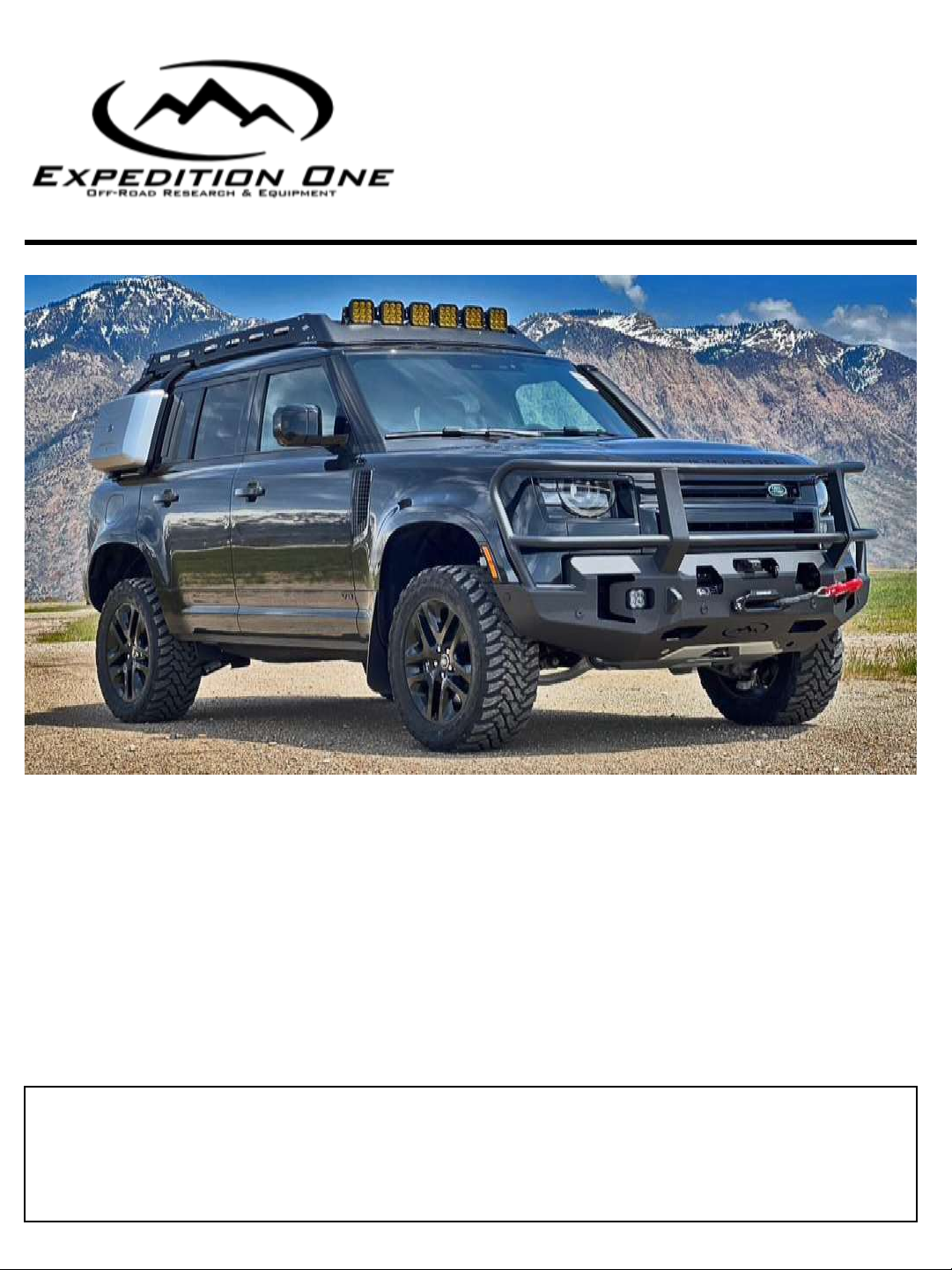
2020+ LAND ROVER
DEFENDER
P L E A S E R E A D E N T I R E G U I D E B E F O R E I N S T A L L A T I O N
Recommended that you read this entire install guide before installation. Check that all hardware is
present before staring or scheduling an install. This guide is supplemental to mechanical knowledge and
ability. Anyone not familiar with automotive installation should seek professional installation.
I N S T A L L G U I D E
LAST UPDATE 11/15/23 v1
E X P 9 1 1
FRONT BUMPER

INSTALL GUIDE
IMPORTANT INFO/FAQ
I N S T A L L G U I D E A L L
EXPEDITION ONE
113 N. 700 W. BUILDING 5C BAY 1
OGDEN, UT 84404
801-627-2921
INSTALLATION HELP
Please review terms and conditions for details
Recommended purchaser review Welcome Guide at time of purchase for details
Care and Maintenance available at www.exp-one.com/resources
We do our best to offer timely assistance with your installation questions however as most of our team
members are primarily engaged in the manufacturing process and packaging processes, we do not
currently offer a tech for on-demand calls and inquiries. For the more technical installs or installs that
are time-sensitive in nature, we would recommend our customers seek out the services of professional
shops with experience specific to aftermarket bumpers that can better meet your needs. We are happy
to make recommendations to you on shops familiar with our products in your area. We do our best to
respond to installation questions within 24-48 hours of contact as much as possible. Long-distance
problem assessment can be difficult, so photos and videos are often required for us to best assist you.
We highly recommend your initial contact regarding installation questions include both close-up and full
photos, detailed descriptions using our part descriptions as much as possible, and video. This enables us
to better assist without having the ability to see the install difficulties directly and assist you as quickly
as possible.
NOTE
Expedition One does not guarantee fitment with other aftermarket products, or reinstallation of take off
OEM parts.
Expedition One is NOT RESPONSIBLE for damage to paint or powder coating, items assembled in error
during installation or costs associated with install
OEM manufacture model refreshes/updates, factory build location and suppliers may cause variations in
fitment or installation and can not be verified, vehicle to vehicle .
*This product contains chemicals known to the state of California to cause birth defects or other reproductive harm. For more
information go to www.p65warnings.gov*
GSA# GS-30F-013CA
*This product contains chemicals known to the state of California to cause birth defects or other reproductive harm.
For more information go to www.p65warnings.gov*
INSTALL GUIDE
IMPORTANT INFO/FAQ
I N S T A L L G U I D E A L L
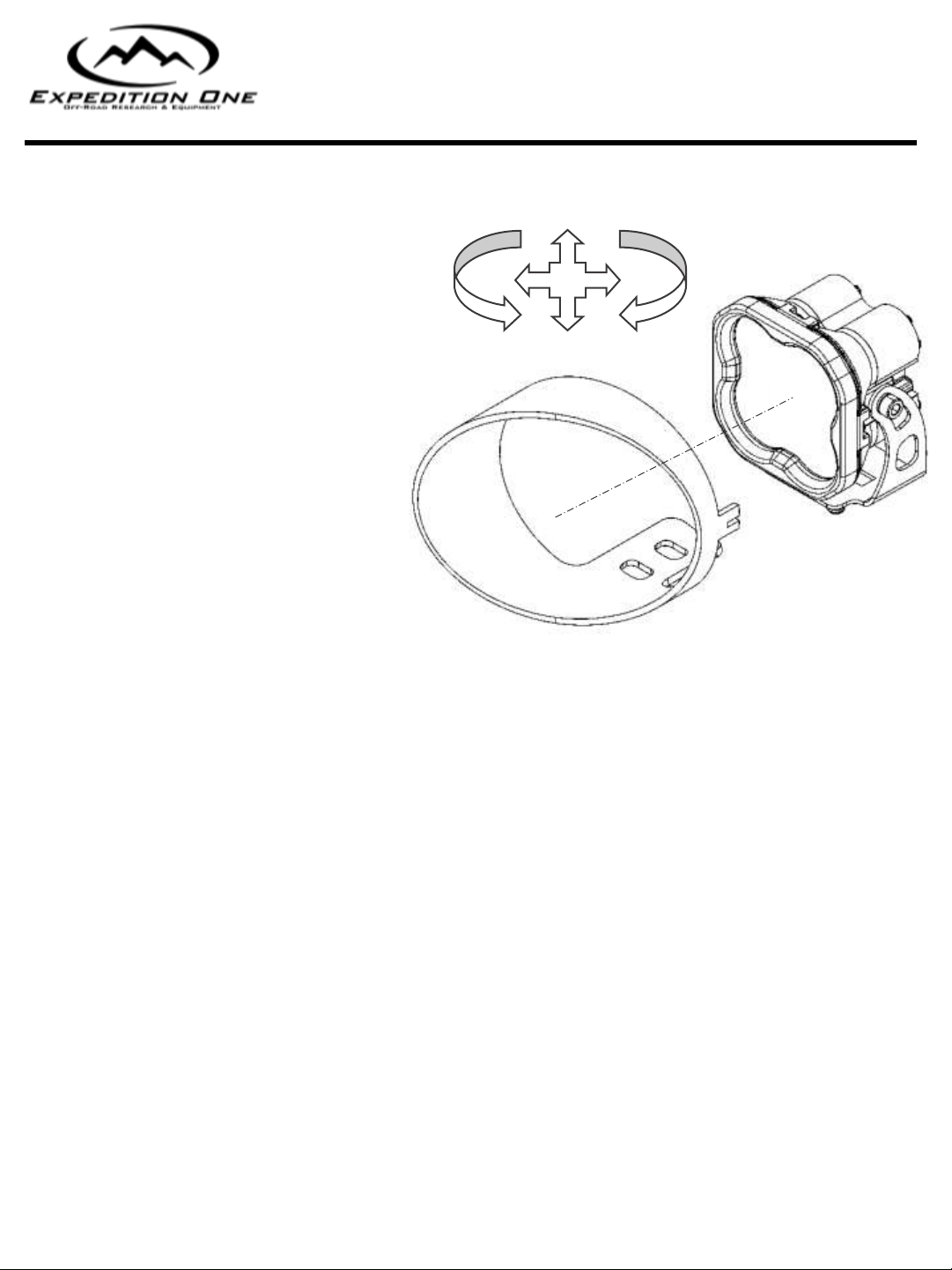
LIGHTPORTS
To give you a wide range of options from
various brands and designs, the light ports
were designed to be as universal as
possible. Not all mounts or designs will fit
exactly and may require the use of shims,
spacers, light manufacture mounts or
different hardware to mount. Reuse of OEM
light is limited to select bumpers and will
come with provided hardware to reinstall. It
is recommended that lights be purchased
with the bumper in hand to gain the best
fitment. We DO NOT manufacture the lights,
provided wiring, or instructions on how to
connect to the OEM harness.
EXAMPLE SHOWN –LIGHT PORTS VARY
WINCHES
We use the most common bolt patterning but cannot guarantee your particular winch will fit. Because there
are so many different brands on the market for winches, we typically recommend you wait until you have
your bumper in-hand and ideally even installed to have specific measurements for best fit for your
application. Integrated and Non-Integrated solenoid fitment varies by vehicle, model, and engine. Non-
integrated solenoids will need to be relocated to an open location with-in the bumper, engine bay, or other
open location. We DO NOT provide mounts or instruction for relocation of the solenoid. Most bumpers use a
foot forward mount and will require the winch to be clocked ( see winch manufacture for details). Winch
plates or direct mounting locations will be provided with the bumper, see install guide for details. See winch
manufacture for hardware, associated parts, or fairleads. . We DO NOT manufacture the winch, provided
wiring, or instructions on how to connect to the vehicles power.
AFTERMARKET or OEM PRODUCTS
We DO NOT guarantee fitment or installation of any aftermarket, third party or OEM parts, accessories, or
hardware. This includes items such as lighting, winches, skids, lifts, suspension, and accessory mounts.
Access to all brands, manufactures and country of origin specific parts is limited or impossible during the
product development stage and subsequent new or modified revisions of said products including OEM design
changes or refreshes. It is recommended you have the product in hand and installed before modifying with
other aftermarket parts. Consult forums or other sources to gain any first hand knowledge of other products
others have installed.
INSTALL GUIDE
HARDWARE INFO
I N S T A L L G U I D E
HARDWARE
Please review for details and installation. Figures or data may vary. Leave all accessible hardware loose for
installation and tighten all hardware after everything is installed on the vehicle. Check and retighten all
hardware after the first 100 miles and/or after off roading. Some hardware locations do not require being
tightened to spec due to there design, location or material attachment (including rubber, plastic, and
aluminum). Over tightening may break or damage parts. Torque spec may vary, amounts listed are generic.
A L L
HARDWARE TORQUE SPEC –FT.-LBS.
SIZE SOCKET
WRENCH
GRADE 5
M- 8.8
GRADE 8
M –10.9
#8 1/4" X
#10 5/16”
1/4" 7/16” 6-8 9-10
5/16” 1/2" 13-14 18-20
3/8” 9/16” 23-26 33-37
7/16” 5/8” 37-41 52-58
1/2" 3/4" 57-64 80-90
9/16” 13/16” 82-91 115-129
5/8” 15/16” 112-118 159-180
3/4" 1-1/8” 200-223 282-315
7/8” 1-5/16” 322-355 454-501
1” 36MM X
M6 10MM 9-10 13-15
M8 13MM 22-24 32-35
M10 15MM 44-49 64-72
M12 18MM 76-83 112-123
GRADE 5
GRADE 8
CLASS 8.8
CLASS 10.9
NOTE - Extra hardware may be left over due
to model or option specific items that may
not be required for the install.
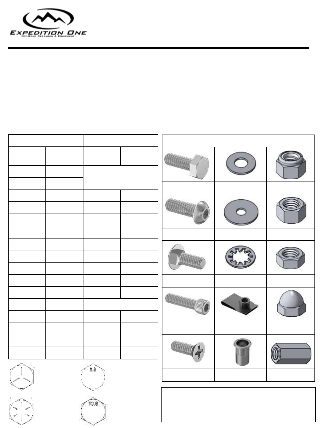
TYPES OF HARDWARE
HEX CAP BOLT WASHER NYLOC NUT
BUTTON HEAD BOLT FENDER WASHER HEX NUT
CARRIAGE BOLT INTERNAL TOOTH JAM NUT
SOCKET CAP BOLT CLIP NUT ACORN NUT
FLAT HEAD SCREW RIVET NUT COUPLING
INSTALL GUIDE
HARDWARE GUIDE
I N S T A L L G U I D E E X P 9 1 1
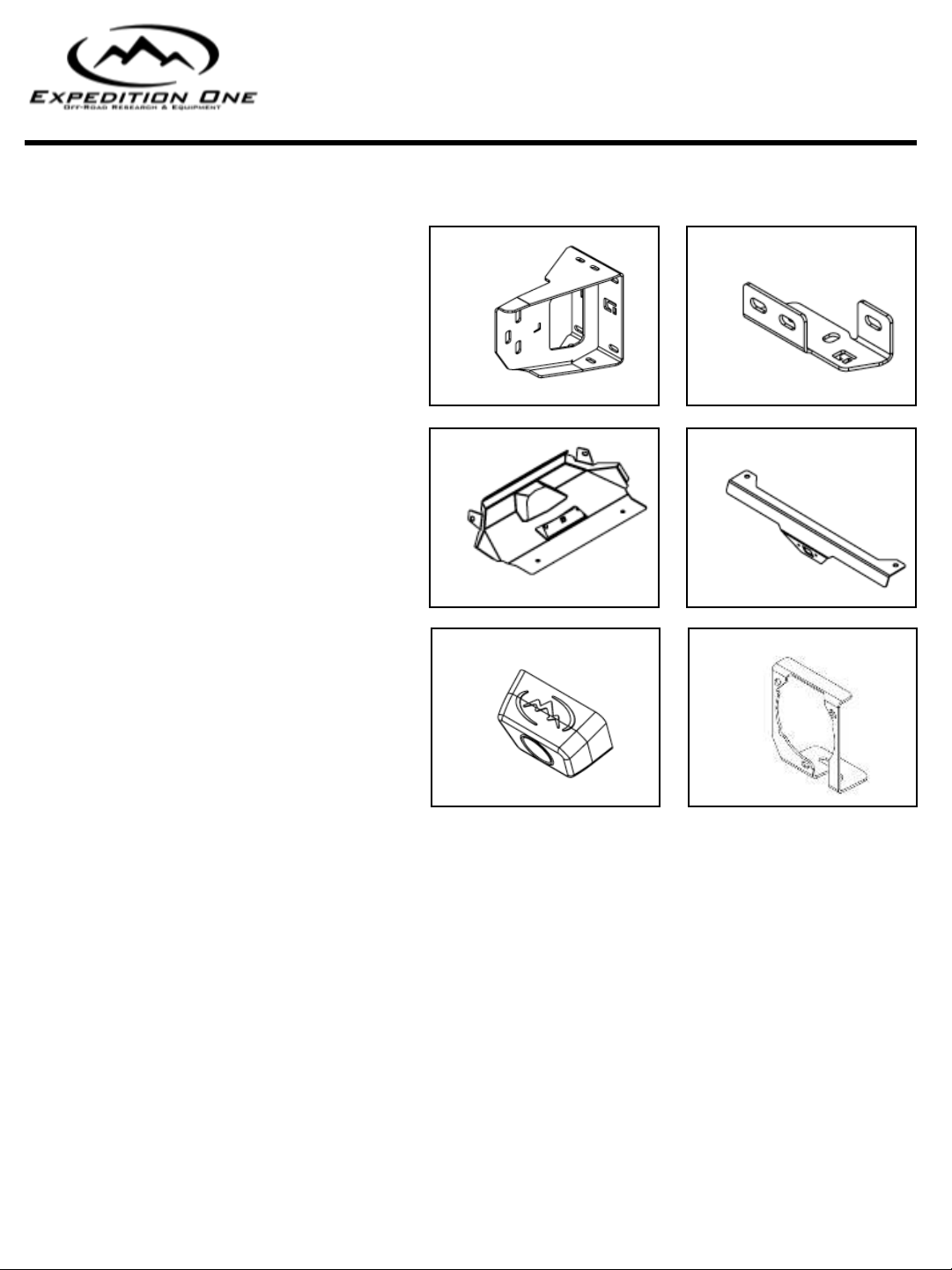
BUMPER
ABumper Mount Bracket 2
BIntercooler Bracket 2
CSkid Plate 1
DCamera Relocation Bracket 1
A
B
C
D
E
F
ECamera Mount 1
FOEM Fog Light Bracket 2
NOTE - Extra hardware may be left over due to model or option specific items that may not be required for the install.
Hardware Kit 1
1/4” – 20 x 3/4” Button Head 8
1/4” – 20 Nyloc Nut 8
5/16” - 18 x 1” Hex cap 4
5/16”- 18 x 1” Carriage Bolt 2
5/16” – 18 Nyloc 6
5/16” USS Washer 10
3/8”-16 X 2 1/2” Button Head Bolt 2
3/8”-16 Nyloc Nut 2
3/8” USS Washer 2
Intercooler Spacer 14
1/2”-13 X 1 1/2” Carriage Bolt 6
1/2”-13 Nyloc Nut 6
1/2” USS Washer 6
Carriage Bolt Retainer 2
Sensor Bezel 6
Wire Ties 10
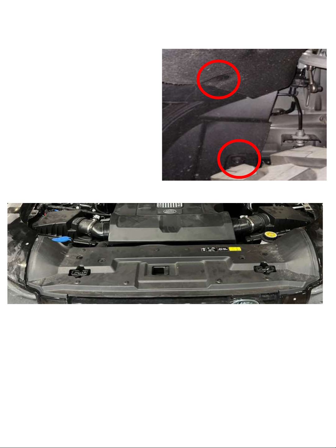
1 - REMOVE OEM BUMPER HARDWARE
Remove the front bumper OEM hardware from the front wheel wells on each side of the vehicle. Extra
locations may need to be unbolted to flex the fender liner (or completely remove the trim) for bumper
removal, access and installation.
Unbolt the OEM hardware from the top of the grille as circled below. Save all hardware, it will be reinstalled.
2 –WIRING CONNECTIONS
Disconnect all wiring at the top of the grille,, grille shutter and main harness connect point. The OEM
lights and sensors should remain attached to the bumper as part of the harness.
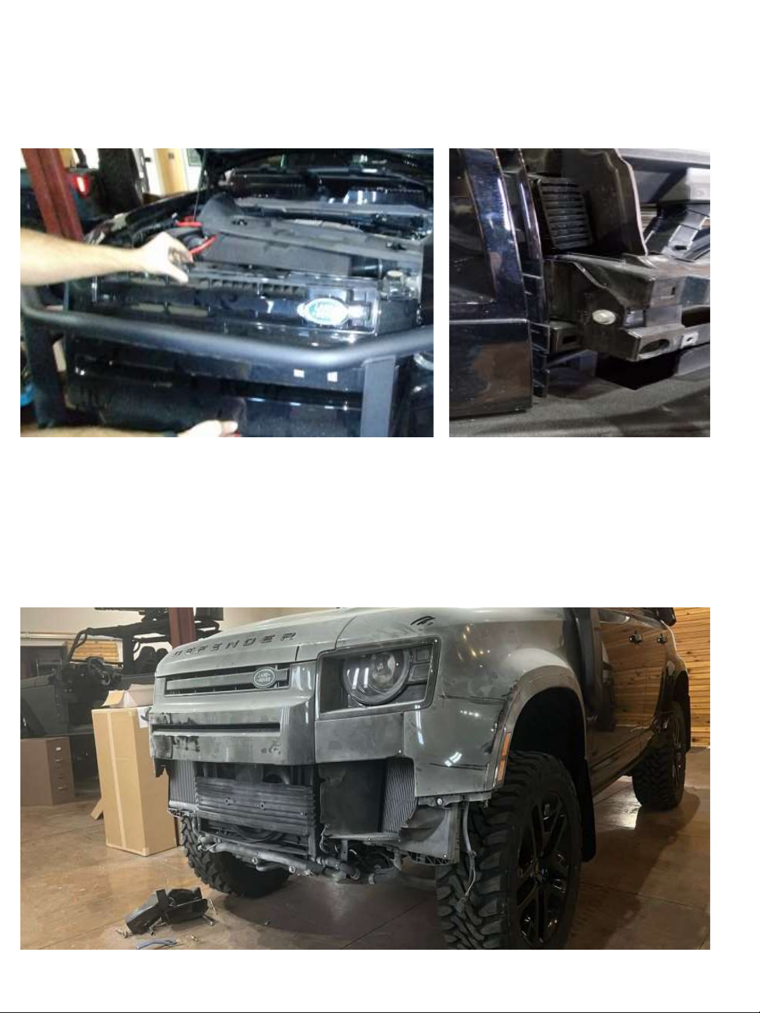
3 –GRILLE REMOVAL
Check for any remaining hardware connecting the bumper. Undo the clips running down the edge near
the headlights. Remove the center by pulling it away from the top. Save all hardware for reinstallation
After the bumper is installed.
4 –BUMPER REMOVAL
Disconnect the bumper panels from the vehicle (finished result below). Remember to disconnect the
parking sensors from the bezels and the front camera. Unbolt the large crash bar and skid plate from
the front. Save all hardware for installation of new bumper.
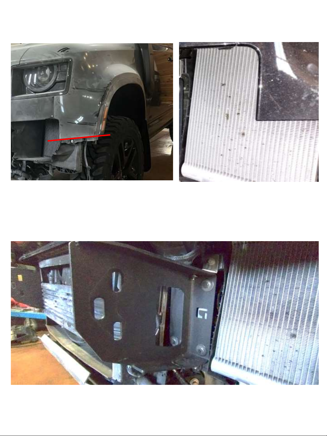
Trim the underside of the fender as shown and remove the intercooler shrouds.
5 –FENDER TRIMMING
6 –REINFORCEMENT BRACKET INSTALLATION
Attach the reinforcement bracket to the frame as shown. Mount using the original hardware. Leave all
hardware loose for adjustment.
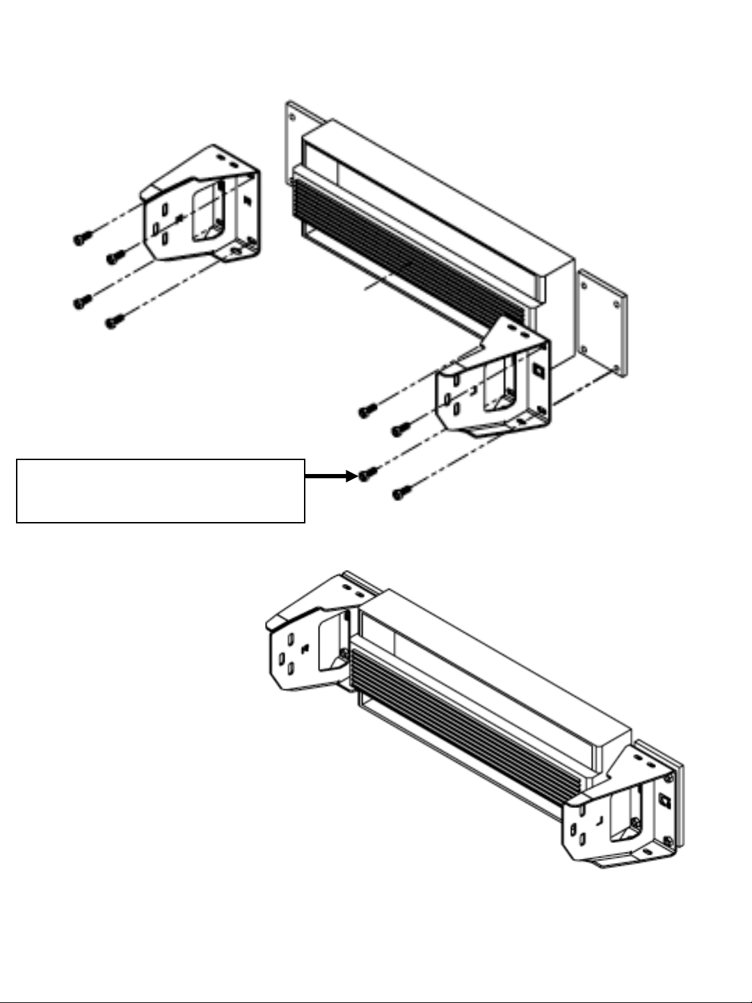
6 –CONTINUED
OEM HARDWARE 4
L - Attach bracket to the
driver side (US Market).
R - Attach bracket to the
passenger side (US Market).
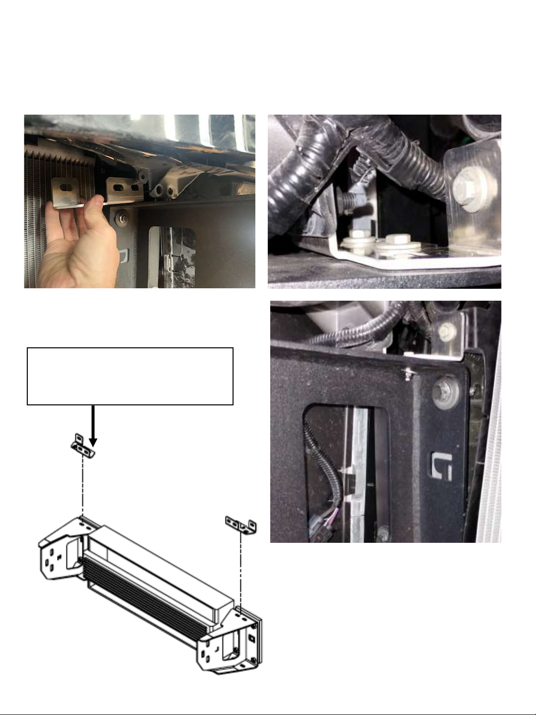
7 –INTERCOOLER BRACKET INSTALLATION
Attach the intercooler bracket on top of the frame mounts and connect to the intercoolers tabs and OEM
frame point as shown. Mount using the provided 5/16” and OEM hardware.
5/16” - 18 x 1” Hex cap 4
5/16” – 18 Nyloc 4
5/16“ USS Washer 8
Indice
Altri manuali Expedition One Accessori per automobili

Expedition One
Expedition One NATO CAN GEN 3 Manuale utente

Expedition One
Expedition One GERI GEN 2 Manuale utente

Expedition One
Expedition One EXPDSTC01 Manuale utente

Expedition One
Expedition One Mule Front Bumper Manuale utente

Expedition One
Expedition One DSTC Manuale utente

Expedition One
Expedition One 4RFJ-LADDER Manuale utente

Expedition One
Expedition One HI-LIFT GEN 3 Manuale utente

Expedition One
Expedition One HI-LIFT/PULL PAL GEN 2 Manuale utente

Expedition One
Expedition One JK 3rd Brake Light Manuale utente

Expedition One
Expedition One BRONCO STC REAR 2021 Plus Manuale utente


