
EZspyCam EPC-500 Series Manuale utente
INSTRUCTION MANUAL
#EPC-500 Series
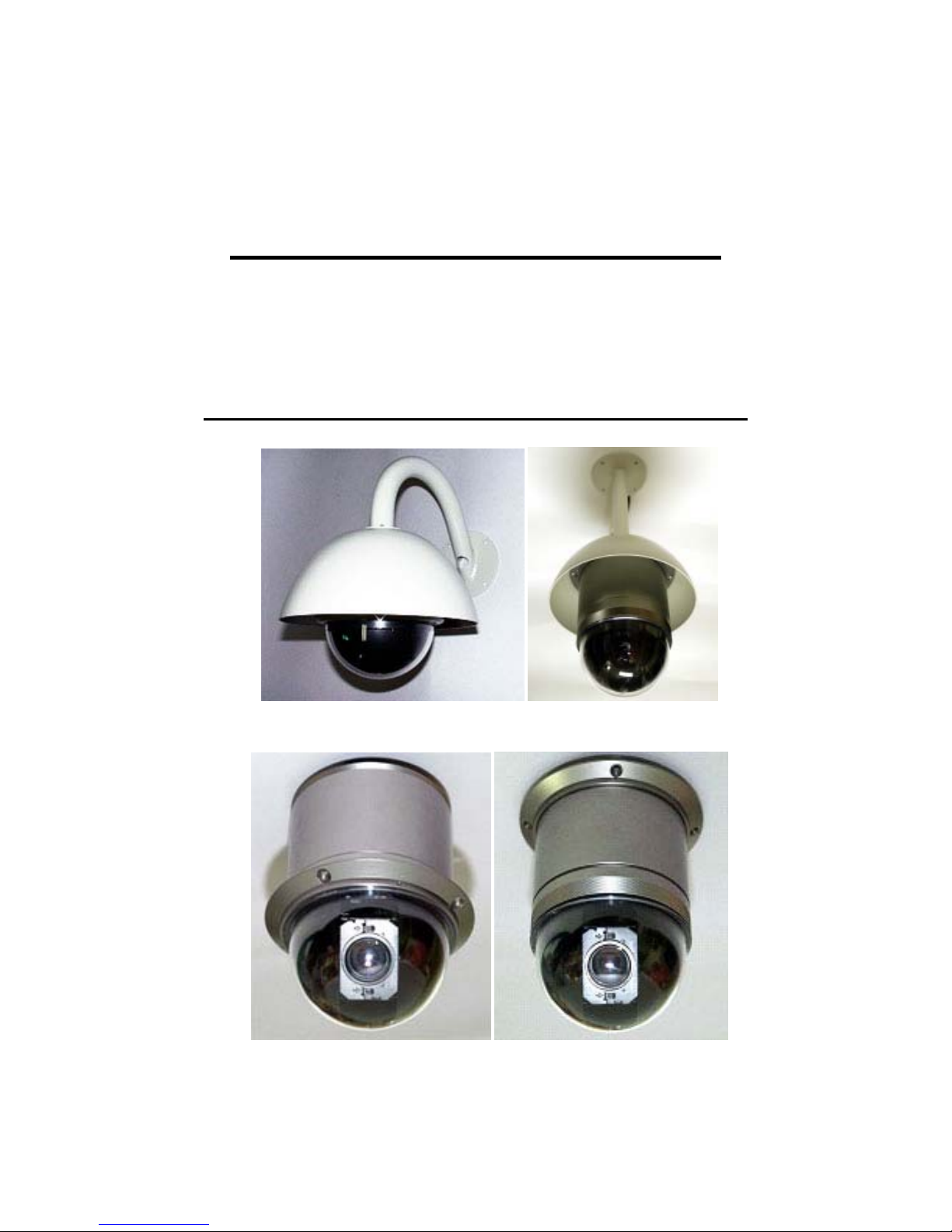
High-Speed Vandalproof Dome Camera
Outdoor Weatherproof Bracket
Indoor Surface MountIndoor Surface Mount
2
Camera Specification
• 1/4” Color CCD, 410 K Pixels
• MAX. 270 × /220x /160x with 10x Digital zoom
• Day & Night – Day True Color/Night-0.01 B/W (270x)
• Wide Dynamic Range Function
High Speed & Silent Motion
• MAX. 360˚/sec High Panning Speed and Continuous Rotation
• Silent with Very Little Vibration
• Simultaneous Pan/Tilt Interpolation Movement
High Accuracy & Long Life Cycle
• Adapted Blush-less DC Motor to Enhance Life Cycle
• Optical Encoder Feedback System for Accurate Control
Compact Design
• ∅130 Mini Dome Housing
PTZ Control
• RS-485 Communication, MAX 256 Multi-drop
• PELCO-D Protocol
Other Functions
• 128 Preset Points with Alphanumeric Label
• Auto Preset – Swing, Pattern, Group
• MIC. Input & Line Output for Audio Interface
Features
3
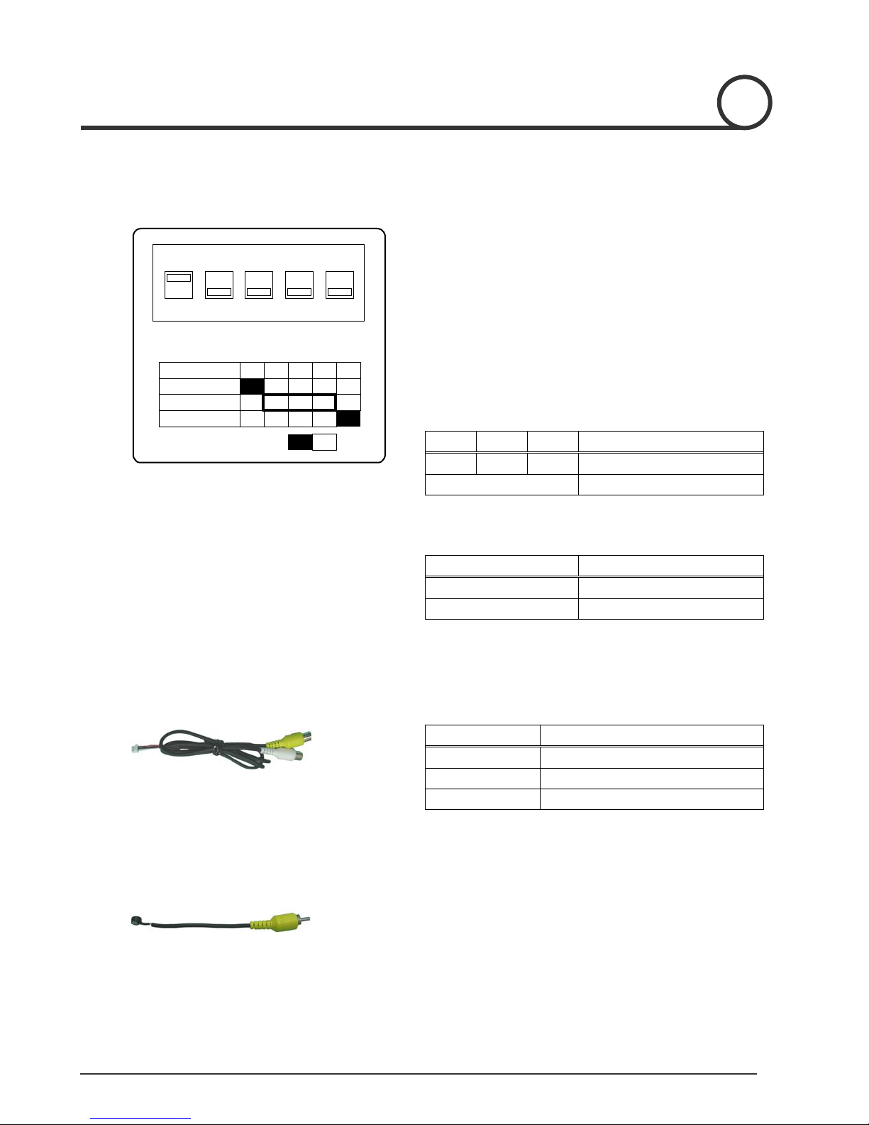
SW 2 : Termination Resistance, Protocol, and Video Format Setting
12345
ON
SW2
SW2:Protocol / Video Setting
NO. 1 2 3 4 5
Termination
Protocol
Video PAL
Off
On
MIC. In / Audio Out cable
MIC. cable
•Termination Resistance: Pin 1
The termination resistor is used for multi-drop connections
where two or more speed dome cameras are connected to a
controller on a communication line consecutively. Turn on
the termination resistance switch of both the nearest camera
and the farthest camera in the communication line.
•Protocol Setting: Pin 2~4
Pin 2 Pin 3 Pin 4 Protocol
Off Off Off PELCO-D
Others Reserved
•Video Format Setting: Pin 5
Pin 5 Video Format
Off NTSC
On PAL
•MIC. In / Audio Out cable
Connector Description
3 Pin Terminal Connect to camera body
RCA yellow MIC. In
RCA white Line Out
•MIC. Cable
Connect MIC. Jack to MIC. In connector
4
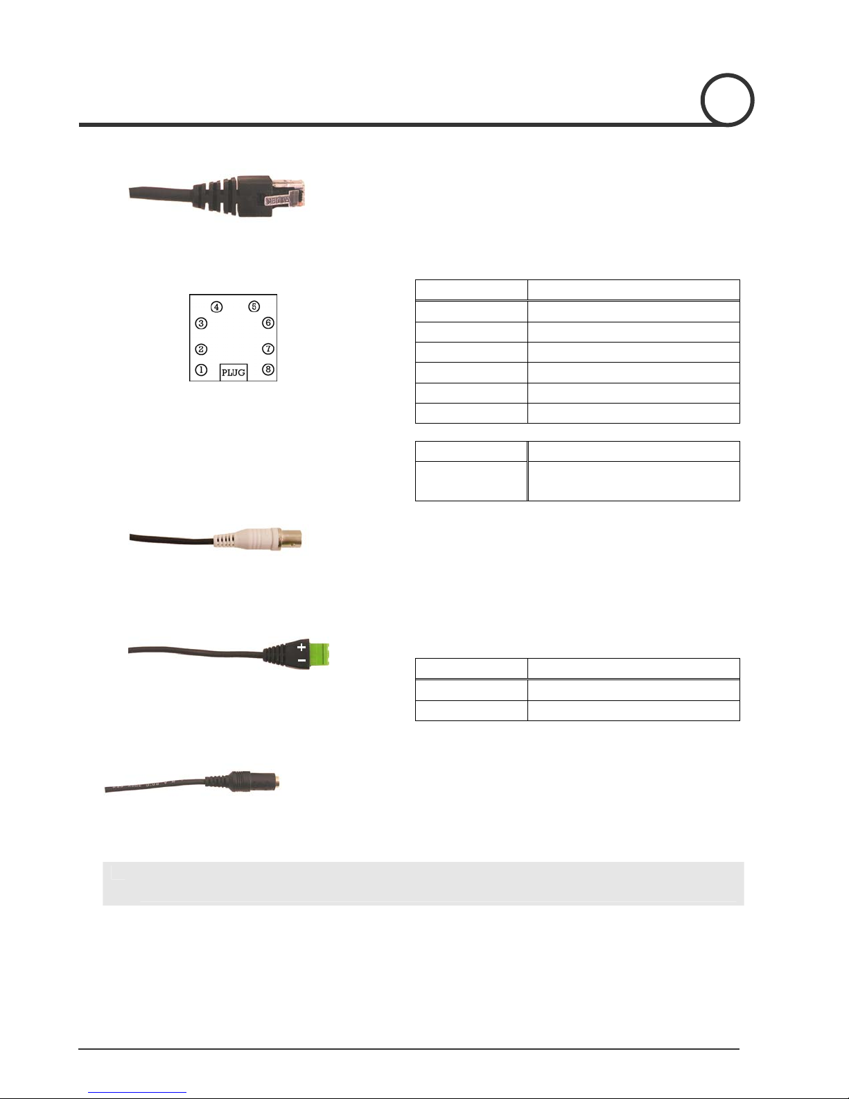
I/O Connector
I/O Module
BNC Connector for Video Out (Indoor)
RS-485 Communication Connector (Indoor)
Power Connector (Indoor)
L With Outdoor Housing, connect Power Input, Video Output, RS-485 cable to the PCB of
Outdoor Housing.
•Video out BNC connector
Connect to units such as monitor, VCR and etc.
•RS-485 Communication Connector
Connector Signal
+ D+
− D−
•Power Input Connector
Rated power input is AC 24V 1.5A. without Fan & Heater.
Rated power input is AC 24V 2A with Fan & Heater.
•I/O Connector
Connect to I/O module.
•I/O Module
Pin Signal
1 Sensor Input 1 +
2 Sensor Input 2 +
3 Sensor Input Ground
4 Not Used
5,6 Relay Output 1
7,8 Relay Output 2
Sensor Input +5V, 10mA
Relay Output AC125V 0.6A Max
DC110V 0.6A Max
5
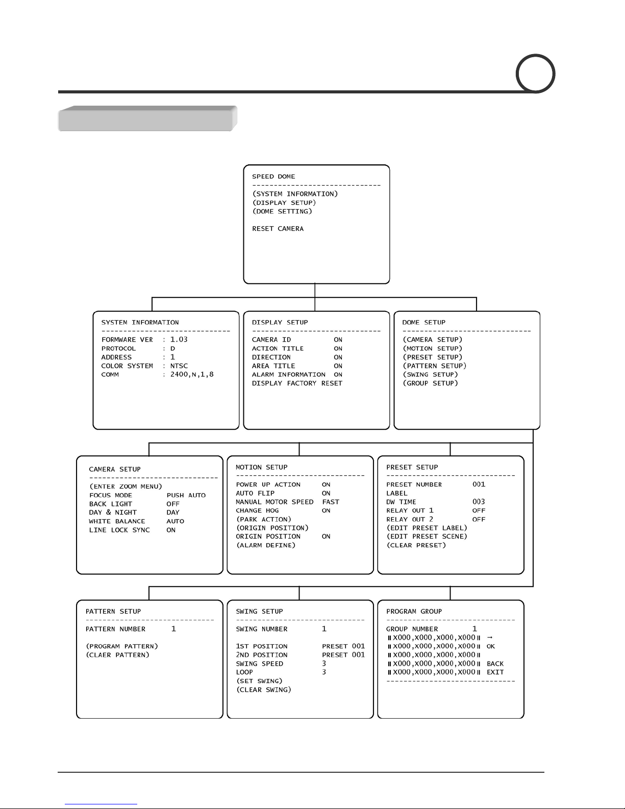
Main
Setup Menu Structure
MENU STRUCTURE

6
Zoom Camera Setup
MENU STRUCTURE

7
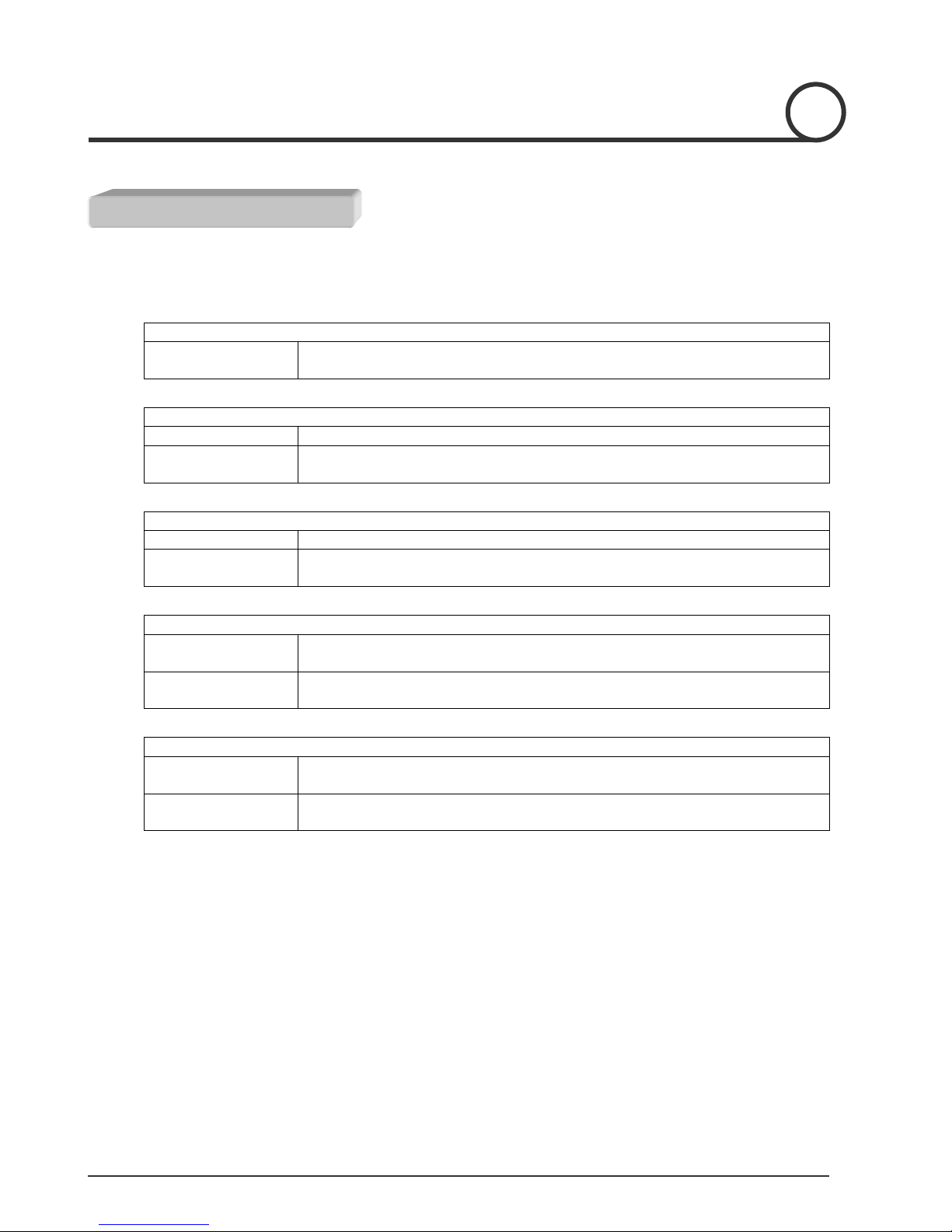
Motion Setup
Preset Setup
MENU STRUCTURE
8
For ‘PELCO-D protocol version 5.0 or higher version’ controller user.
Menu
Enter Menu Enter Numerical Key 95 and Pattern key
[95] + [Pattern]
Swing
Set Swing Enter Menu to set Swing function
Run Swing Enter Numerical Key 11~18 and Pattern key
[Number] + [Pattern]
Group
Set Group Enter Menu to set Group function
Run Group Enter Numerical Key 21~28 and Pattern key
[Number] + [Pattern]
Preset
Set Preset Key in 1 – 128 and hold Preset Key for more than 2 seconds
[Number] + [Preset] (More than 2 seconds)
Run Preset Key in 1 – 128 and hold Preset Key for less than 2 seconds
[Number] + [Preset] (Less than 2 seconds)
Pattern
Set Pattern Key in 1 – 4 and hold Pattern Key for more than 2 seconds
[Number] + [Pattern] (More than 2 seconds)
Run Pattern Key in 1 – 4 and hold Pattern Key for less than 2 seconds
[Number] + [Pattern] (Less than 2 seconds)
Macro
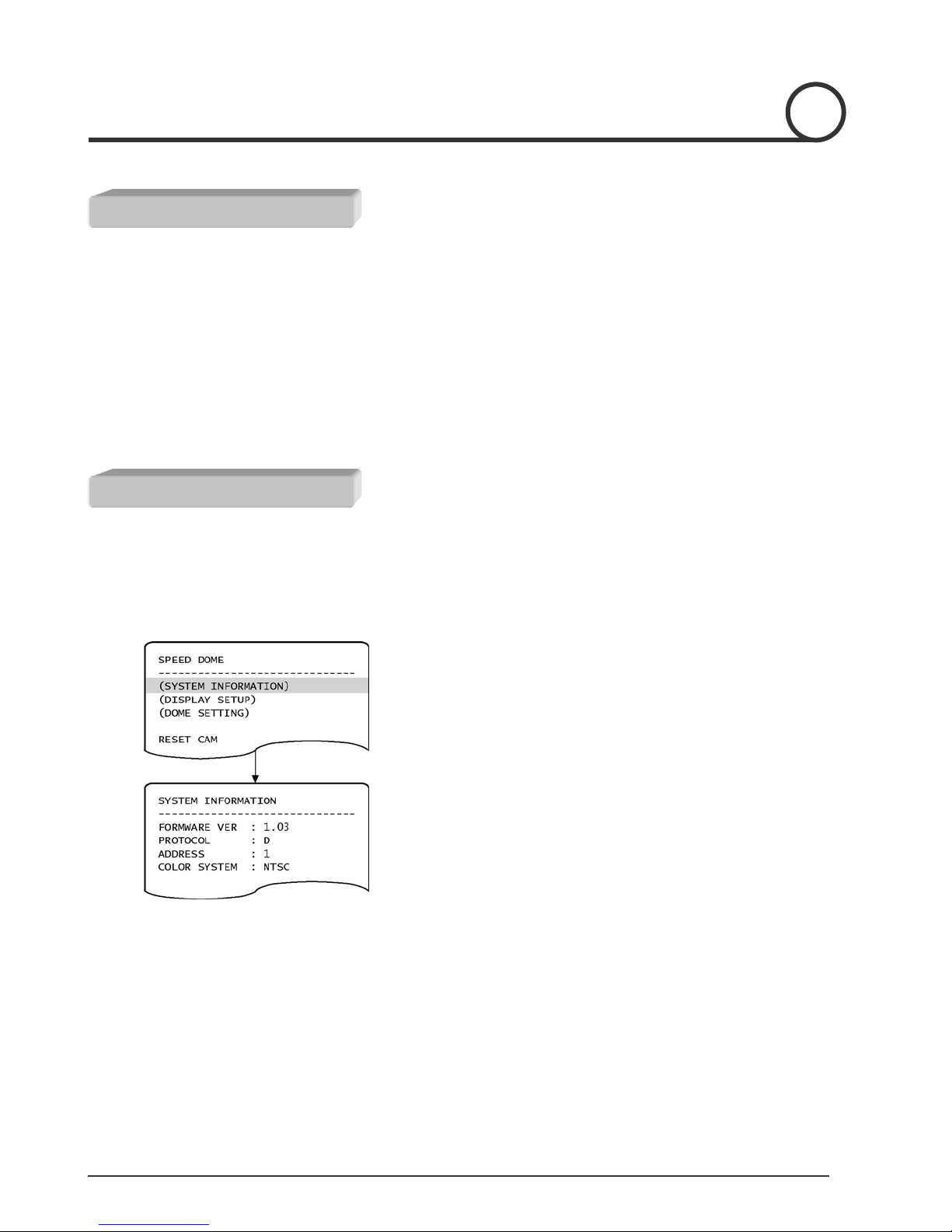
MENU STRUCTURE
9
• Menu heading in parenthesis ( ) contain sub-menu
• Use NEAR key to enter into sub-menu and use FAR key to return to upper menu
• Use JOYSTICK to scroll up & down the cursor in menu
• Use NEAR key to move the cursor at selection value location
• Use JOYSTICK to change the set value except CAMERA ZOOM MENU
• In CAMERA ZOOM MENU, Use NEAR or FAR key to change the set value
L
Menu heading in parenthesis () contain sub-menu
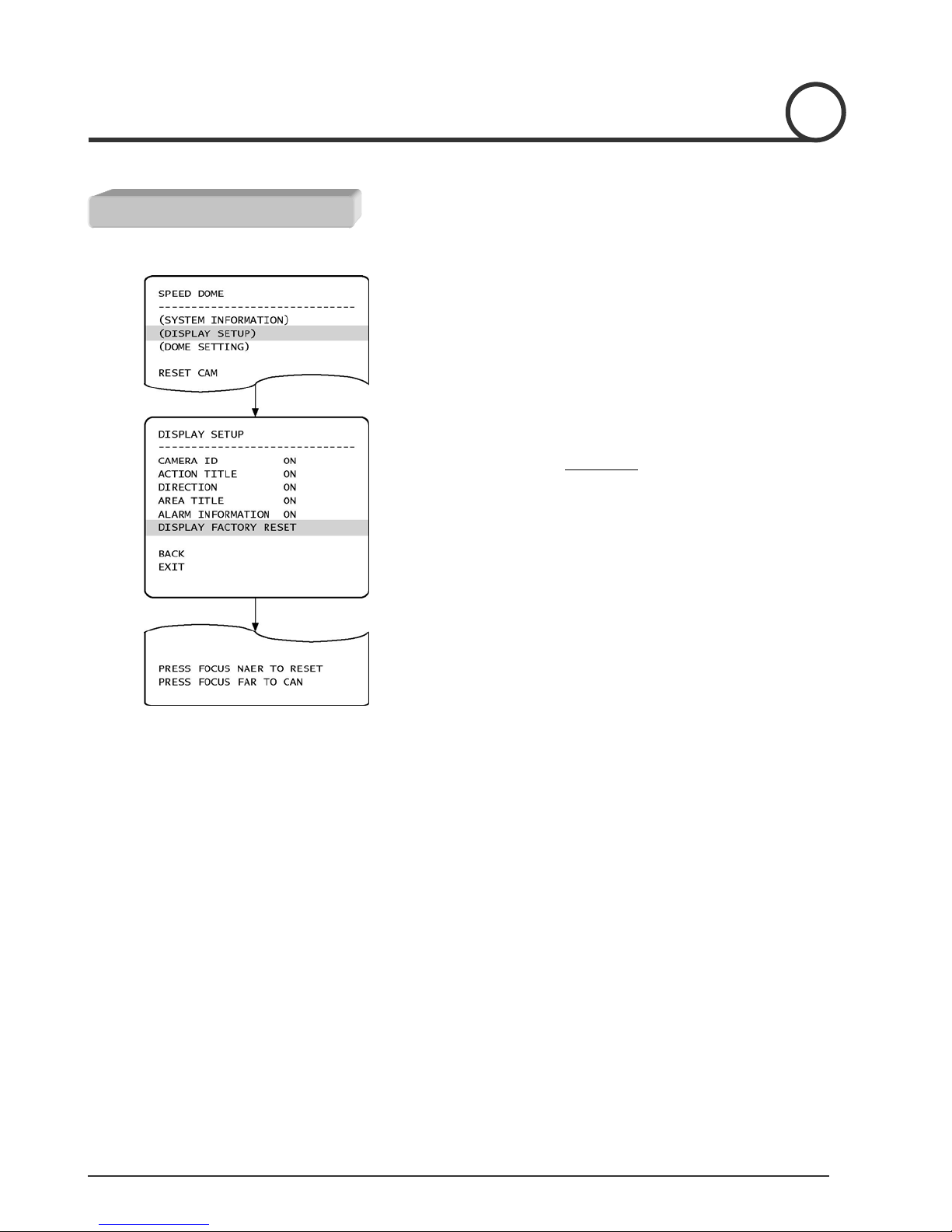
System Information Menu
MENU DESCRIPTION
• Shows System Information
○
1 Locate the cursor at (SYSTEM INFORMATION) menu
○
2 Press NEAR key to enter into sub-menu
Key & Joystick Usage
10
•To enter into Display Setup menu
○
1Locate the cursor at (DISPLAY SETUP) menu
○
2Press NEAR key to enter into sub-menu
• Camera ID Shows the address of the camera
• Action Title Shows the current action
Example) PRESET 001 on screen: Preset 1 is activated
• Direction Shows the position of camera by angle from origin
position
• Area Title Shows the label of preset position when it is ON
• Alarm Info Shows the status of alarm input/output
• To reset to original Factory Default Settings
○
1 Press NEAR key at (DISPLAY FACTORY RESET) menu
○
2 Press NEAR or FAR key in sub-menu
L The default factory reset value of entire configuration is 'ON'
Display Setup
MENU DESCRIPTION
Indice


