FAFCO 500 Series Manuale utente

500 Series
Closed Loop
Solar Hot Water System
Installation Manual
Made in the U.S.A.
Note: This manual provides a detailed, step-by-step procedure for installing the Solar
Water-Heating System. The directions should be followed properly, and only recommended
components and hardware should be used. This will ensure a trouble-free system that will
maintain the warranty while providing solar energy and savings.
FAFCO © 2010

Introduction ..........................................1
Safety .................................................. 2
Code and Certication Requirements.. 3
Parts List..............................................4
Optional Kits ........................................5
Tools Required.....................................5
Overview..............................................6
Installation Checklist .......................... 13
1: Site Selection and Planning ........ 14
2: Roof Mounting ............................. 15
3: Tank Plumbing ............................17
4: ICM Installation ........................... 20
Table of Contents
Introduction
The Solar Water Heating System is designed to provide a signicant portion of the water-heating energy required in a
typical home. Solar energy is absorbed by the solar collectors, and heated water is circulated through the water heater.
Heated water is drawn from the water heater by various household xtures and appliances, such as a clothes washer,
dishwasher, bath, shower, and other xtures.
System performance is affected by available solar energy, the solar collectors’ installed pitch and orientation,
groundwater and ambient air temperatures, and the daily household hot water demand comprised of bath, kitchen,
and laundry use. These conditions, which may vary from home to home even in the same neighborhood, determine
how much energy your solar system will save.
1
5: Tubing & Sensor
Installation - Below Roof ............. 20
6: Tubing & Sensor
Installation - On Roof .................. 21
7: System Fill ..................................22
8: System Start-up .......................... 22
9: System Operation ....................... 24
10: Troubleshooting .......................... 25
Maintenance ...................................... 25
Specications .................................... 26
Required Labels.................................27
Optional Kit Instructions..................... 28

2
Dangerous Heights
Solar collector(s) are often installed on the roof of a building. Unless you’re familiar with working on roofs and
have the proper ladders and safety equipment for such work, you should hire someone with the necessary
experience to do the installation. Failure to observe safe practices on a roof or other elevated structures may
result in falling and serious injury. Working alone increases the chance of an accident happening. Be sure to
have help or someone nearby to assist you.
High Voltage
Some aspects of installation involve working around and with high voltage. Electrical connections to the hot water
heater (if electric) are typically 240 VAC and CAN KILL YOU. Use precautions and ensure that all electricity is
shut off to the area in which you’re working. Use the breaker box and remove the breaker if you have to. Check
with a voltmeter to verify the voltage is off before contacting any electrical connections. Consult with a licensed
electrician if you have any doubts about the process. Check your local building codes.
High Water Pressure and Temperature
Electric and gas water heaters operate at high water pressure and temperature. Be sure to turn off your water
supply and open drain valves to depressurize the system before unthreading or cutting into any part of the water
heater plumbing. Consult a licensed plumber if you have any doubts. Check your local building codes.
Hot water is dangerous. Water temperature to the home
can be regulated by adjusting the temperature control
valve. The recommended set point is 120° F. There is
a scald potential if the temperature control valve is set
too high.
Hot water can produce rst degree burns within:
• 120° F (49°C) more than 5 minutes
• 130° F (54°C) at 20 seconds
• 140° F (60°C) at 3 seconds
• 150° F (66°C) at 1-1/2 seconds
• 160° F (71°C) at less than 1 second
! WARNING !
WATER TEMPERATURE REGULATION
Safety
Page 21 of this manual contains instructions to mix a minimum 35% FAFCO HTF with potable water. Use of any other
heat-transfer uid will void warranty, and may result in poor performance and/or equipment damage. This mixture is suf-
cient for any freezing conditions per Section 21.5 of the ASHRAE Handbook, Fundamentals which states, “If the uid is
being used to prevent equipment damage during idle periods in cold weather, such as winterizing coils in an HVAC system,
35% propylene glycol is sufcient. These concentrations will allow the uid to freeze. As the uid freezes, it forms a slush
that expands and ows into any available space. Expansion volume must be included with this type of protection. If the
application requires that the uid remain entirely liquid, use a concentration with a freezing point 5oF below the lowest ex-
pected temperature. Avoid excessive glycol concentration because it increases initial cost and adversely affects the uid’s
physical properties.” Freeze protection is conservatively estimated down to -20oF. Freeze tolerance limits are based
upon an assumed set of environmental conditions. MSDS is available at www.fafco.com for information on disposal
and First Aid. FAFCO system is overheat protected and has little metal in contact with uid. It therefore does not promote
deposits, corrosion, or degradation of uid mixture.
HEAT TRANSFER FLUID AND FREEZE PROTECTION

Code requirements
Refer to the local authority having jurisdiction, such as the local building department or utility, to ensure all installation work meets applicable require-
ments. Use the FAFCO permit package, available for download at www.fafco.com, to submit to the local authority having jurisdiction for permitting.
All installation work should be performed by a properly licensed contractor. Backup water heater and/or storage tank must be listed and labeled by
an accredited listing organization, meet national standards, be labeled with maximum temperature and pressure, and have minimum R-12 insulation.
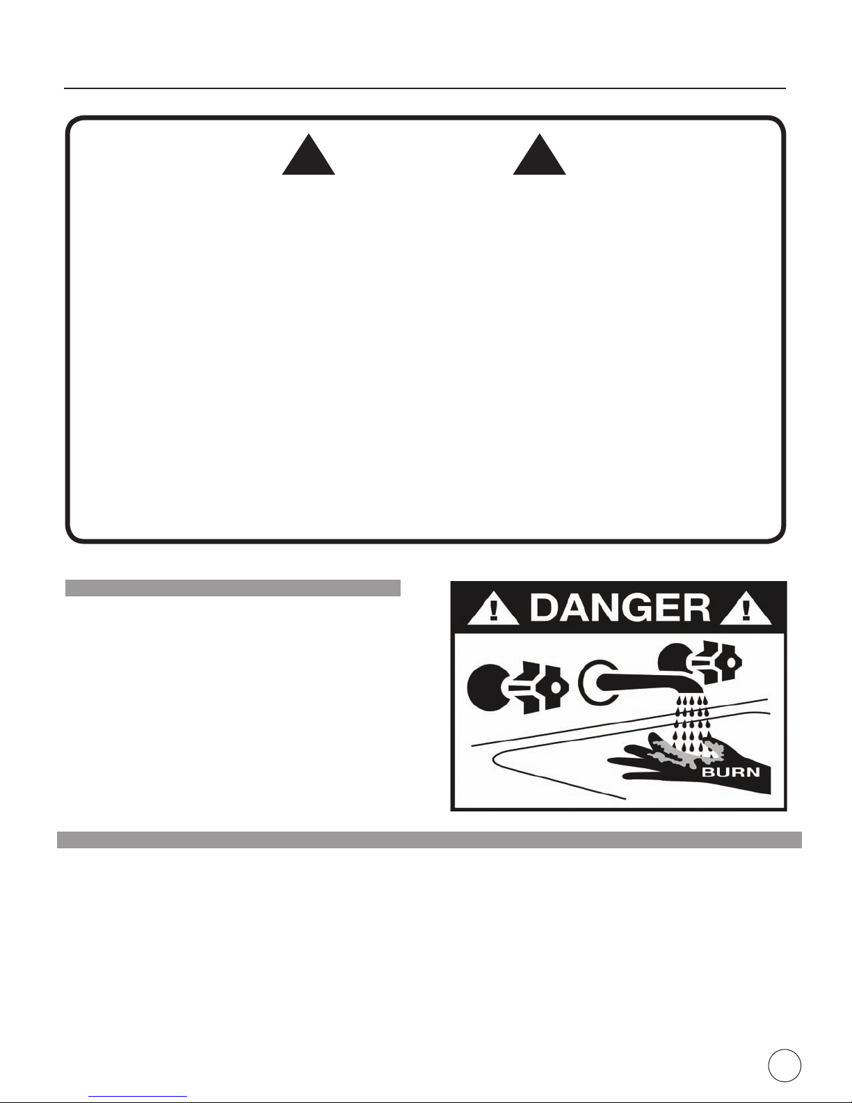
Do not remove, bypass, or alter temperature pressure relief valve from backup water heater and/or storage tank.
Certication requirements
Refer to the local authority having jurisdiction and incentive providers for certication requirements.
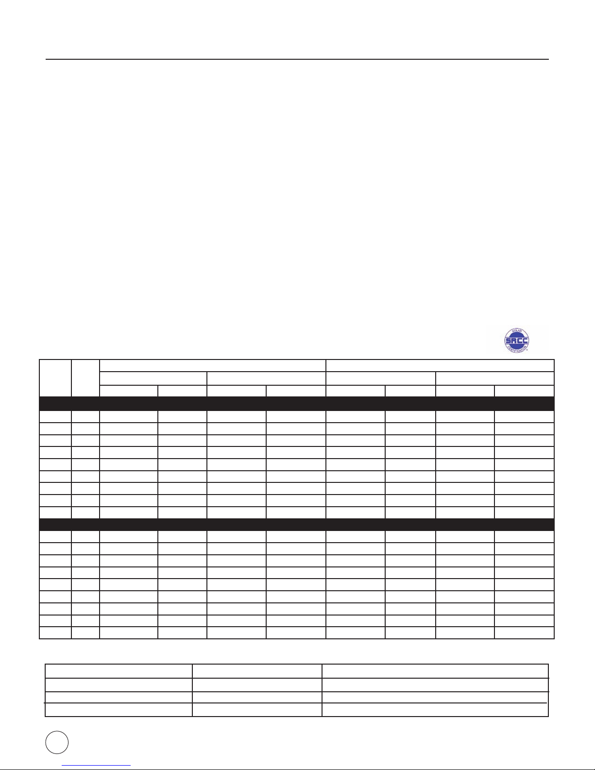
FAFCO solar collectors and systems listed in Specications, page 25, are certied by the Solar Rating and Certication Corporation (SRCC), a
nationally recognized certication for solar water heating collectors and systems. The solar energy system described in this manual, when properly
installed and maintained, meets the minimum standards established by SRCC. This certication does not imply endorsement or warranty of this
product by SRCC. Specic minimum SRCC installation requirements are listed below:
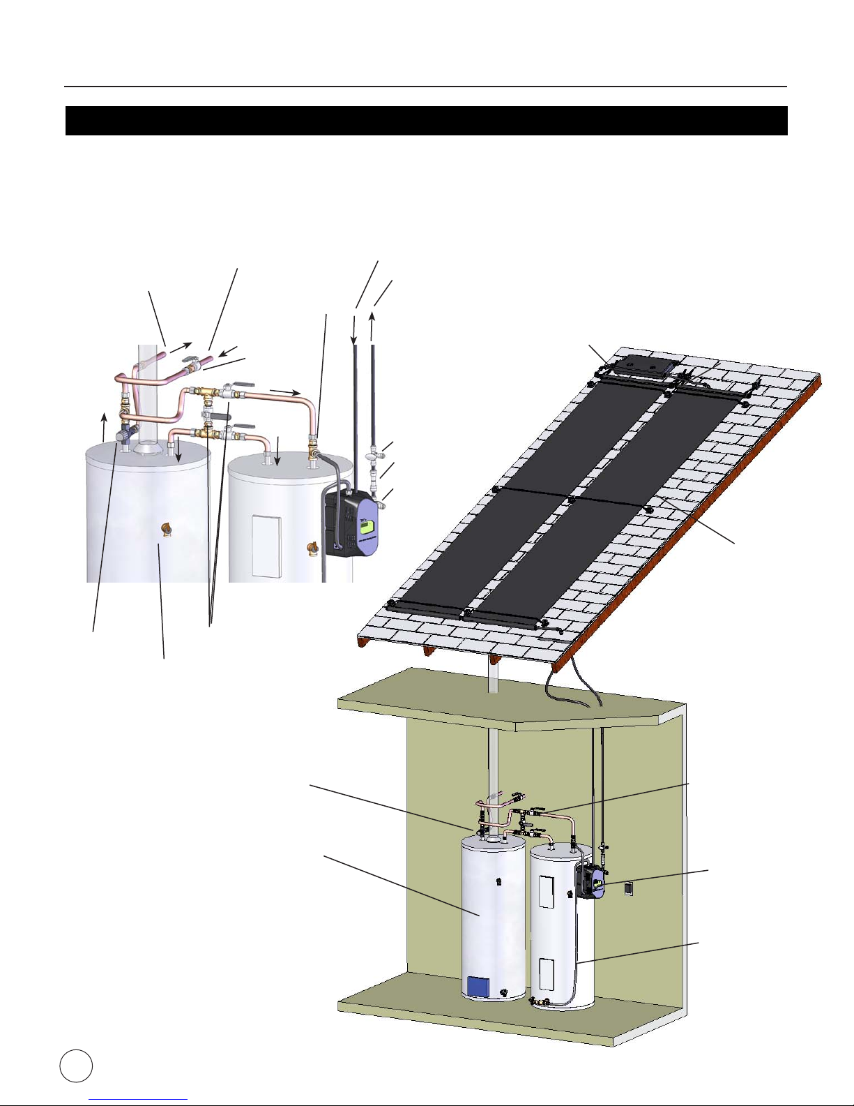
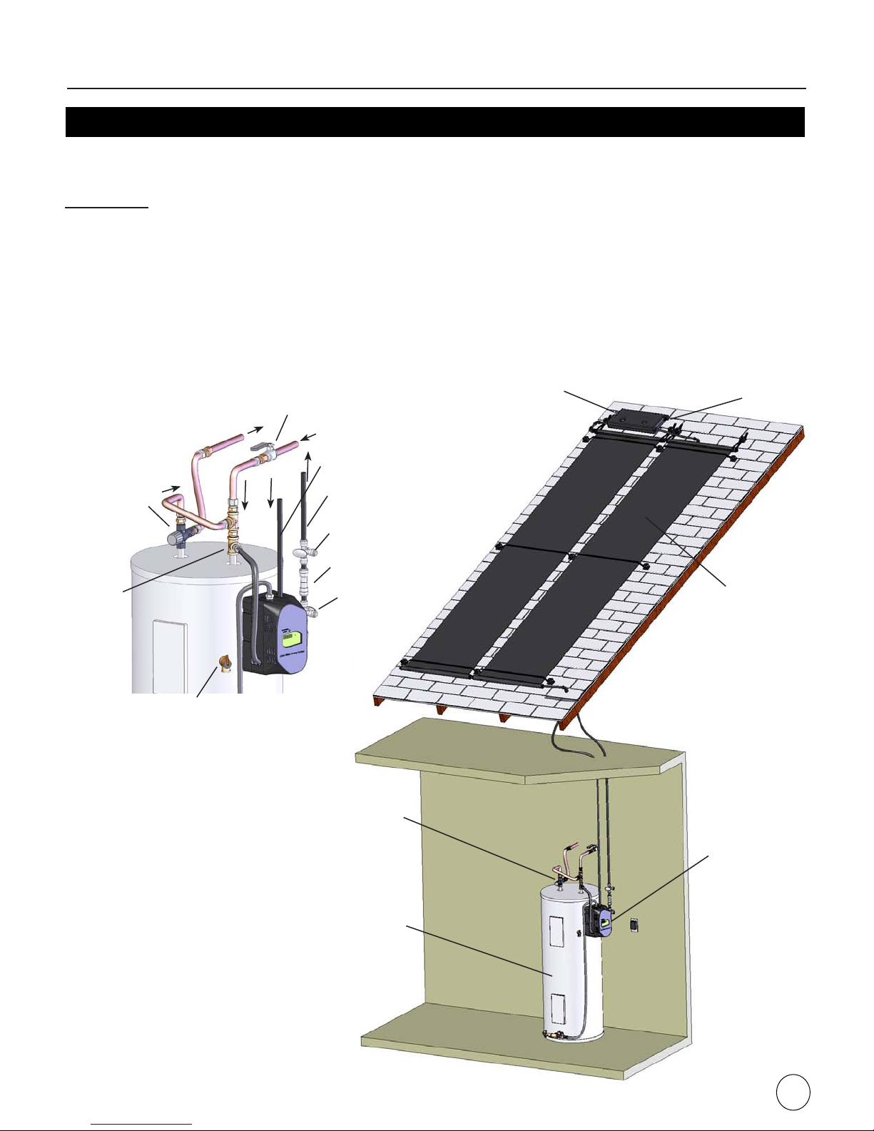
1. Building penetrations do not impair enclosure function.
2. Building penetrations do not allow insect or vermin intrusion.
3. Building penetrations meet applicable codes and National Roong Contractors Assoc. practices.
4. Structural members penetrated by solar system components meet code.
5. Building materials adjacent to solar components are not exposed to elevated temperatures.
6. Collector mounting is capable of maintaining tilt and azimuth.
7. No excessive shading of collectors.
8. Hangers provide correct tube support.
9. Hangers provide correct tube pitch.
10. Hangers do not compress insulation.
11. Control sensors and wiring are protected.
12. Penetrations through re-rated assemblies do not reduce re resistance below code.
SRCC model numbers
Up to date model numbers can be found at SRCC’s website, www.solar-rating.org.
OG-100:
- 2’X12’ COLLECTOR: SRCC MODEL 2007030A AND 2’X8’ COLLECTOR: SRCC MODEL 2007030B
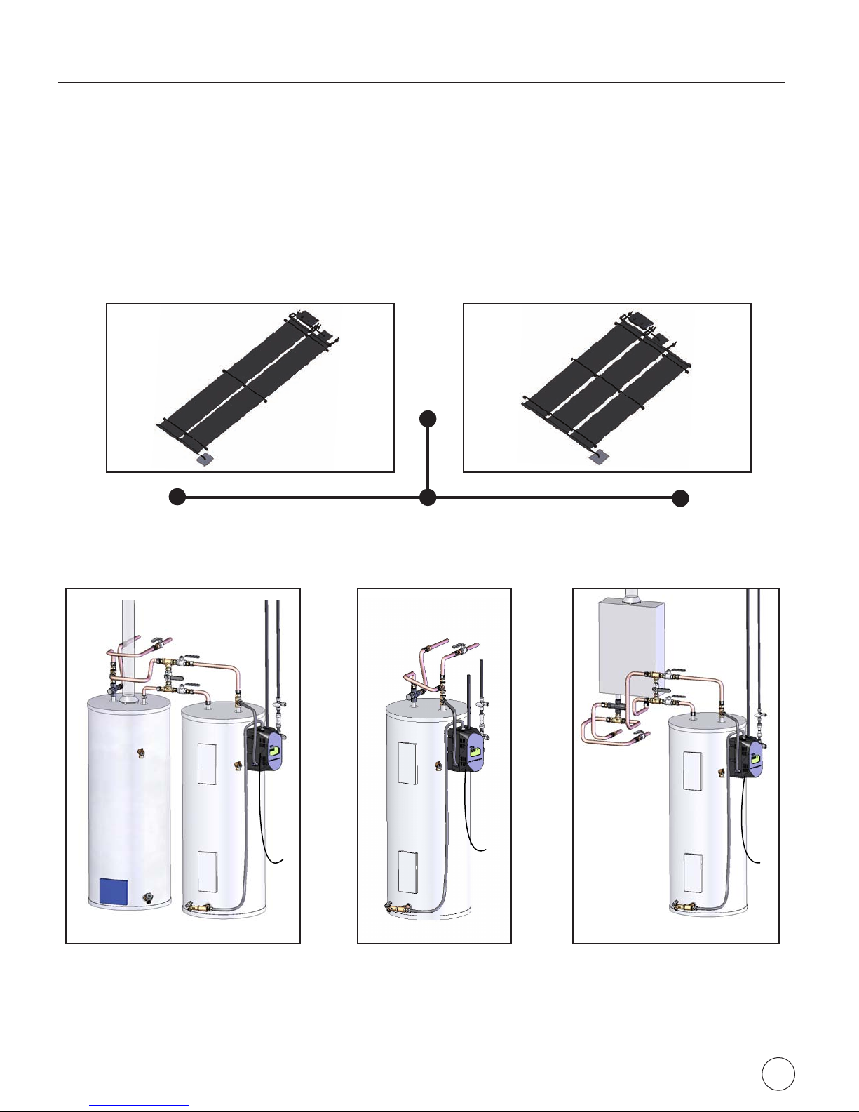
OG-300:
3
Code and Certication Requirements
Power Supply
* All brand and product names appearing in this manual are registered trademarks of their respective companies.
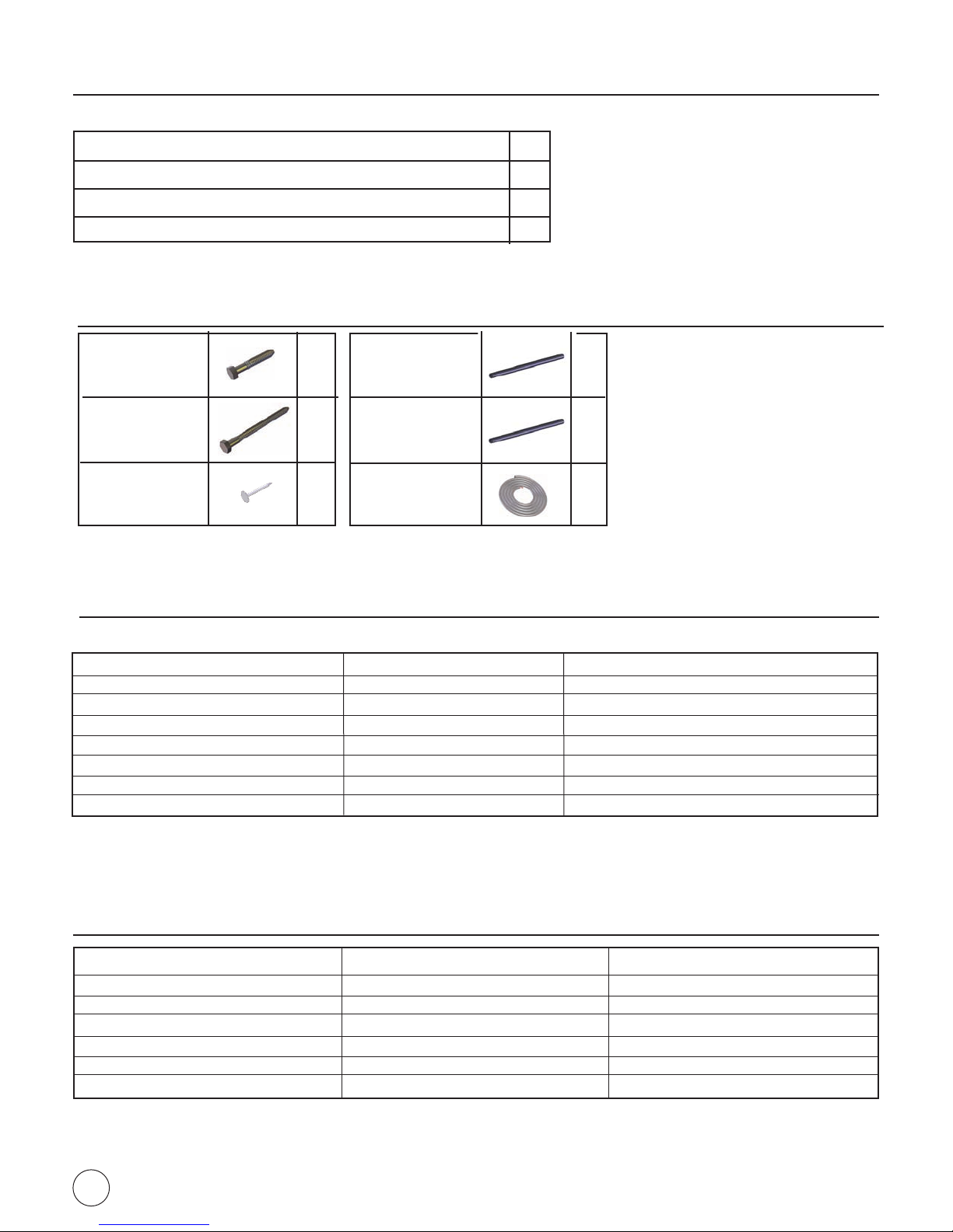
Expected operating conditions
Temperature
Pressure
Flowrate
MEASUREMENT SYSTEM ACCESS POINT EXPECTED VALUE
Controller display
Expansion reservior
Solar or Potable Loop
DT greater than 10oF when operating
Less than 1 psi
1 to 2 gpm
Solar
Collector
Area
(sq-ft)
Solar
Tank
Volume
(gal)
2’x12’ Collectors 2’x8’ Collectors
Electric Water Heater Gas Water Heater Electric Water Heater Gas Water Heater
Dual Tank Single Tank Dual Tank On-Demand Dual Tank Single Tank Dual Tank On-Demand
A/C
48 50 AC24UX2-50E-50S AC24UX2-50E AC24UX2-50G-50S AC24UX2-TG-50S AC16UX3-50E-50S AC16UX3-50E AC16UX3-50G-50S AC16UX3-TG-50S
48 80 AC24UX2-50E-80S AC24UX2-80E AC24UX2-50G-80S AC24UX2-TG-80S AC16UX3-50E-80S AC16UX3-80E AC16UX3-50G-80S AC16UX3-TG-80S
48 120 - AC24UX2-120E - AC24UX2-TG-120S - AC16UX3-120E - AC16UX3-TG-120S
96 50 AC24UX4-50E-50S AC24UX4-50E AC24UX4-50G-50S AC24UX4-TG-50S AC16UX6-50E-50S AC16UX6-50E AC16UX6-50G-50S AC16UX6-TG-50S
96 80 AC24UX4-50E-80S AC24UX4-80E AC24UX4-50G-80S AC24UX4-TG-80S AC16UX6-50E-80S AC16UX6-80E AC16UX6-50G-80S AC16UX6-TG-80S
96 120 - AC24UX4-120E - AC24UX4-TG-120S - AC16UX6-120E - AC16UX6-TG-120S
144 50 AC24UX6-50E-50S AC24UX6-50E AC24UX6-50G-50S AC24UX6-TG-50S AC16UX9-50E-50S AC16UX9-50E AC16UX9-50G-50S AC16UX9-TG-50S
144 80 AC24UX6-50E-80S AC24UX6-80E AC24UX6-50G-80S AC24UX6-TG-80S AC24UX6-50E-80S AC16UX9-80E AC16UX9-50G-80S AC16UX9-TG-80S
144 120 - AC24UX6-120E - AC24UX6-TG-120S - AC16UX9-120E - AC16UX9-TG-120S
PV
48 50 PV24UX2-50E-50S PV24UX2-50E PV24UX2-50G-50S PV24UX2-TG-50S PV16UX3-50E-50S PV16UX3-50E PV16UX3-50G-50S PV16UX3-TG-50S
48 80 PV24UX2-50E-80S PV24UX2-80E PV24UX2-50G-80S PV24UX2-TG-80S PV16UX3-50E-80S PV16UX3-80E PV16UX3-50G-80S PV16UX3-TG-80S
48 120 - PV24UX2-120E - PV24UX2-TG-120S - PV16UX3-120E - PV16UX3-TG-120S
96 50 PV24UX4-50E-50S PV24UX4-50E PV24UX4-50G-50S PV24UX4-TG-50S PV16UX6-50E-50S PV16UX6-50E PV16UX6-50G-50S PV16UX6-TG-50S
96 80 PV24UX4-50E-80S PV24UX4-80E PV24UX4-50G-80S PV24UX4-TG-80S PV16UX6-50E-80S PV16UX6-80E PV16UX6-50G-80S PV16UX6-TG-80S
96 120 - PV24UX4-120E - PV24UX4-TG-120S - PV16UX6-120E - PV16UX6-TG-120S
144 50 PV24UX6-50E-50S PV24UX6-50E PV24UX6-50G-50S PV24UX6-TG-50S PV24UX6-50E-50S PV16UX9-50E PV16UX9-50G-50S PV16UX9-TG-50S
144 80 PV24UX6-50E-80S PV24UX6-80E PV24UX6-50G-80S PV24UX6-TG-80S PV24UX6-50E-80S PV16UX9-80E PV16UX9-50G-80S PV16UX9-TG-80S
144 120 - PV24UX6-120E - PV24UX6-TG-120S - PV16UX9-120E - PV16UX9-TG-120S

4
Power Supply
18*
28*
24*
4*
Roof Kit: Two 2’ x 12’ Collectors PN 08881 or Three 2’ x 8’ Collectors PN 08911
Mounting bases
PN 06918
13
13
2
Mounting caps
PN 06919
Roof jack
PN 08211
Roof sealant,
10 oz. tube
PN 08229
Mounting Strap,
40’ roll, PN 08907 1
1
20
Collet clips
PN 08819
Roof Sensor
PN 08380
Wire connector
PN 08359
1
20
1
2
Roof sensor
sleeve PN 08910
Panel plug
PN 08837
Support liner
PN 08520 1
Elbow ttings
PN 08441 6
22
Reservoir Fender
washer, PN 08884
2
Rubber grommet
Roof Jack, PN 08190
Collector connectors
3-1/2” L, PN 08883
18*
* Quantities in upper left denote 2’x12’ collectors and lower right denote 2’x8’ collectors
Parts list
COMPONENT QTY.
BRAND
- Differential controller
Solar collector (2’x8’) or
Expansion reservoir
3
1
Integrated Circulation Module (ICM)
1
Heat Transfer Fluid 3 gallons
1
08890
MODEL
FAFCO
FAFCO
Solar collector (2’x12’) 08840
08790
FAFCO
- Pump
08783
FAFCO
- Heat exchanger 08782
FAFCO
08795
FAFCO
1
PV Panel Kit (For PV System Only) 08844
FAFCO
08897
FAFCO
08797
FAFCO
A.O. Smith or
equivalent
Conservationist,
Promax Plus, or
equivalent
Solar Storage tank (not provided)
Image
2
1
1
2
1
08845
FAFCO
- PV Panel
Ground Kit PN 08882
Teon tape roll
PN 07581
1
Fill and drain
valves PN 08836
Flexible hoses
3’ - PN 08834
5’ - PN 08835
Plastic tubing,
80 ft. PN 08613
Tube support
clips PN 08609
2
1
EA
20
Tee, brass, 3/4”
PN 08872
2
Reducer, brass,
3/4” x 1/2”
PN 08862
Check valve,
PN 09003
Nipple, brass, hex,
3/4” PN 08869
2
1
1
Elbow, swivel
PN 08305
Filter, self-clean
PN 08833
Power Supply
PN 08784
Screw, self
tapping, 2-1/2”
PN 08830
1
1
3
1
1Cable ties
PN 08184 4
Sensor
PN 08380
2Nipple, brass,
3/4” x 3”
PN 08863
1
Escutcheon
PN 08462
2
Sensor cable,
50’ PN 08208
1
12
Support liner
PN 08520
12
Collet clips
PN 08819

5
Parts list (Continued)
Tools Required
Channel lock pliers
Two or more ladders
Wire cutters
Cordless power drill
Wire strippers
Hammer
3/4” & 1-1/4” paddle bit
Caulking gun
1/4” drill bit
Tape measure
5/16” & 7/16” socket driver
Stud nder
#2 & #3 Phillips screw driver
Level
3/4” masonry bit (For tile roof)
3/4” male thread tap
Adjustable wrench
Tubing cutter
Safety glasses
1/8” at blade screw driver
Optional Kits
Coltector Lag
screw, stainless
steel, 1/4” x 2”
18
Reservoir Lag
screw, stainless
steel, 1/4” x 3-1/2”
2
Roong nails, 1” 8
Parts NOT Provided
Pipe Insulation,
R-2.6 min, 3/4”
thick min
Tube Insulation,
R-2.6 min, 3/4”
thick min, 5/8” ID
-
-
Tube Insulation
Support
-
Information Kit
1
1
1
2
Installation Manual - PN 08905
Cold Water Valve Position Label - PN 08371
Freeze Protection And Fluid Safety Label - PN 08904
Label attachment zip-ties - PN 08307
Collector Add-On Kit
Tile Roof Installation Kit (TRIK)
Solar Storage Tank Kit (Low lead)
Temperature Control Valve Kit (Low lead)
Coaxial Tank Adapter Conversion Kit
Electric Fill Kit
Tubing Extension Kit, 80 ft.
Tube Repair Kit
Kit Name Kit Number Description
758 (Two 2’x12’) or 759 (Three 2’x8’)
767 (Two 2’x12’) or 769 (Three 2’x8’)
730-1
733
776
777
734
162-1
48 square feet of collectors with 1 gallon HTF. See pg. 33
Anchors and supports collectors on tile roofs. See pg. 36
Connects water heater to solar storage tank, See pg. 19
Valve required by code. See pg. 18
Enables both connections at tank drainport. See pg. 34
Pumps HTF into system. See pg. 22
80 foot of additional tubing for long runs
Rubber plugs for repairing solar collector tubes

6
There are three basic solar water heating system congurations:
• Dual-tank gas or electric
• Single-tank electric
• Single-tank with on-demand gas heater
Components vary based on conguration. Refer to the schematics on the following pages for further details.
Two 2’ x 12’ Solar Collectors
Dual-Tank Single-Tank Single-tank
with
on-demand Heater
Three 2’ x 8’ Solar Collectors
Overview

7
Overview (continued)
DUAL TANK SYSTEM
Solar-heated water in the solar storage tank preheats the water to the electric or gas water heater. A solar storage tank
connection kit (PN 730-1) is available from your supplier to connect the solar storage tank to the electric or gas water
heater.
Temperature
control valve
Water heater
Storage Tank
Integrated
Circulation Module
(ICM)
Bypass
valves
Expansion
reservoir
Self Cleaning Filter
From solar collectors
To solar collectors
Cold water supply
Fill valve
Cold water
shut-off valve
Temperature
Control Valve
Bypass valves
Hot water to home
Drain valve
P/T Valve
Air Vent/Pressure
Relief Valve
Solar collectors
Check valve

8
Overview (continued)
SINGLE TANK SYSTEM
Solar-heated water is stored directly in an electric water heater with a single active upper element, rather than a
separate storage tank.
Electric water heater: An electric water heater can be either be one that is manufactured with only one element, or an electric water heater manufactured with two elements with the bottom element
disconnected. Single element electric water heaters replenish hot water slower than dual element water heaters. Refer to the local plumbing code for minimum water heater size requirements. Code
typically requires that water heaters be sized to meet a minimum “First Hour Rating” based on the number of bedrooms and bathrooms in a home. For single element water heaters that don’t have
published First Hour Ratings, GAMA/AHRI recommends using 0.75 times the water volume which would require that an 80 gallon tank be used in homes as large as 2 bedroom, 2 bath and that a
120 gallon tank be used in larger homes. It is also recommended to install low ow shower heads which can signicantly reduce hot water demand and save water. Raising the thermostat setting
on water heater element can also increase hot water capacity, but doing so may decrease realized energy savings.
Solar collectors
Water heater
Expansion
reservoir
Integrated
Circulation Module
(ICM)
Temperature
Control Valve
Air Vent/Pressure
Relief Valve
From solar collectors
To solar collectors
Hot water to home Cold water supply
Self
Cleaning
Filter
Cold water shut-off valve
Fill valve
Drain valve
P/T Valve
Temperature
Control Valve
Check Valve

9
Solar-heated water in the solar storage tank preheats the water to the gas on-demand water heater. A solar storage
tank connection kit (PN 730-1) is available from your supplier to connect the solar storage tank to the gas on-demand
water heater. For an on-demand water heater to properly work with a solar water heating system, it must have a
temperature-modulating gas burner. A temperature control valve is required for this conguration, but depending on
the brand and model of on-demand heater, the valve placement may vary. Refer to the manufacturer’s instructions for
compatibility with solar water heating systems and proper placement of the temperature control valve.
SYSTEM OVERVIEW
(ON-DEMAND FOR GAS OR ELECTRIC)
SINGLE TANK WITH ON-DEMAND HEATER
Overview (continued)
Temperature
control valve
Gas
On-demand
Heater
Integrated
Circulation Module
(ICM)
Expansion
reservoir
Bypass valves
Polymer Solar
Collector
Storage Tank
Air Vent/Pressure
Relief Valve
Fill valve
Drain valve
Gas
On-demand
Heater
Temperature
control valve
To solar collectors
From solar collectors
Cold
water
supply
Cold water
shut-off
valve
Hot water
to home
Bypass
valves
P/T valve
Self cleaning
lter
Check valve
Indice
Altri manuali FAFCO Sistema idrico
Manuali Sistema idrico popolari di altre marche

Spirotech
Spirotech SPIROVENT SUPERIOR S250 Manuale utente

Culligan
Culligan Aqua-Cleer Aqua-Cleer Advanced Drinking Water... Manuale utente

A.O. Smith
A.O. Smith Dura-Max AJH - 1000A - P Manuale utente

Microline
Microline T.F.C.-4 Manuale

Eureka Forbes
Eureka Forbes Aquaguard Select Manuale utente

Cetetherm
Cetetherm AquaEfficiency Manuale utente


