Ferris Snapper Pro EZ Dump X Manuale
Not for
Reproduction
OPERATOR’S
MANUAL
EZ Dump X & XL
Grass Collection Systems
12 Cu. Ft. & 14 Cu. Ft. Hopper
with Setup Instructions
5103143
Rev F
System
Number Description Fits Models
5600469 14 Cu. Ft. Hopper Kit (w/ Fast-Vac) IS3100Z w/ 61” Mower Deck
5600470 14 Cu. Ft. Hopper Kit (w/ Fast-Vac) S200XT w/ 61” Mower Deck
5600553 14 Cu. Ft. Hopper Kit (w/ Fast-Vac) S800X w/ 61” Mower Deck
5600745 14 Cu. Ft. Hopper Kit (w/ Turbo-Pro Max) IS3100Z w/ 61” Mower Deck
5600746 14 Cu. Ft. Hopper Kit (w/ Turbo-Pro Max) S200XT w/ 61” Mower Deck
5600744 14 Cu. Ft. Hopper Kit (w/ Turbo-Pro Max) S800X w/ 61” Mower Deck
5600754 12 Cu. Ft. Hopper Kit (w/ Fast-Vac) IS3100Z w/ 61” Mower Deck
5600755 12 Cu. Ft. Hopper Kit (w/ Fast-Vac) IS2100Z w/ 61” Mower Deck
S200XT w/ 61” Mower Deck
5600757 12 Cu. Ft. Hopper Kit (w/ Fast-Vac) S150XT w/ 52” Mower Deck
5600758 12 Cu. Ft. Hopper Kit (w/ Fast-Vac) IS2100Z w/ 52” Mower Deck
5600751 12 Cu. Ft. Hopper Kit (w/ Turbo-Pro Max) IS3100Z w/ 61” Mower Deck
5600752 12 Cu. Ft. Hopper Kit (w/ Turbo-Pro Max) IS2100Z w/ 61” Mower Deck
S200XT w/ 61” Mower Deck
5600753 12 Cu. Ft. Hopper Kit (w/ Turbo-Pro Max) IS2100Z w/ 52” Mower Deck
5600756 12 Cu. Ft. Hopper Kit (w/ Turbo-Pro Max) S150XT w/ 52” Mower Deck
5600870 14 Cu. Ft. Hopper Kit (w/ Turbo-Pro Max) IS3200Z w/61” Mower Deck
5600871 14 Cu. Ft. Hopper Kit (w/ Fast-Vac) IS3200Z w/61” Mower Deck

Not for
Reproduction
2www.ferrisindustries.com | www.snapperpro.com
GENERAL INFORMATION
Thank you for purchasing this quality-built Ferris or Snapper Pro product. We’re pleased that you’ve placed your
confidence in the Ferris or Snapper Pro brand. When operated and maintained according to the instructions in
this manual, your Ferris or Snapper Pro product will provide many years of dependable service.
This manual contains safety information to make you aware of the hazards and risks associated with this
machine and how to avoid them. This machine is designed and intended to be used and maintained according
to the manual for finish cutting of established lawns and is not intended for any other purpose. It is important that
you read and understand these instructions thoroughly before attempting to start or operate this equipment.
These setup instructions are to be done in addition to the Blower, Blower Mount and Weight Mount Installation
instructions included in the Turbo-Pro Max or Fast-Vac Grass Collection System instructions included with the
blower mount.
You must observe and obey all safety instructions in the Turbo-Pro Max or Fast-Vac Grass Collection System
instructions along with any safety instructions included in this manual.
The illustrations in this manual are representative and may not exactly match your unit.
DATE PURCHASED
Briggs & Stratton Power Products Group, LLC.
Copyright © 2015 Briggs & Stratton Corporation
Milwaukee, WI, USA. All rights reserved.
FERRIS is a trademark of Briggs & Stratton
Corporation Milwaukee, WI, USA.
SNAPPER PRO is a trademark of Briggs & Stratton
Corporation Milwaukee, WI, USA.
Contact Information:
Briggs & Stratton Power Products Group, LLC.
5375 N. Main St.
Munnsville, NY 13409-4003
(800) 933-6175
www.ferrisindustries.com
www.snapperpro.com
Table of Contents
General Information ........................................... 2
Safety Rules & Information ............................... 3
Installation........................................................... 4
General Operating Instructions ...................... 16
Hopper Removal............................................... 18
Not for
Reproduction
3
SAFETY RULES & INFORMATION
You must observe and obey all safety instructions
in the Turbo-Pro Max or Fast-Vac Grass Collection
System manual included with the Blower Mount in
addition to all safety instructions included in this
manual.
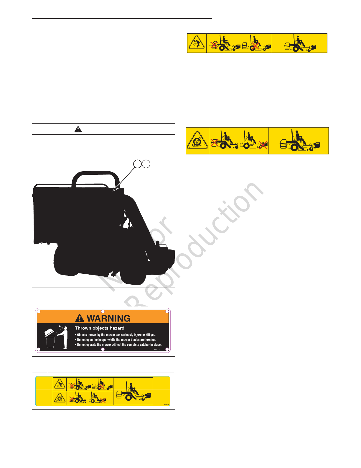
Safety Decals
Before operating your unit, read the safety decals. The
cautions and warnings are for your safety. To avoid a
personal injury or damage to the unit, understand and
follow all safety decals.
Safety Rules & Information
A
WARNING
If any safety decals become worn or damaged, and
cannot be read, order replacement decals from your
local dealer.
B
A. Part Number: 1732820 - “Decal-Warning,
Catcher” (Previous Units with Text Decals)
B. Part Number: 5104315 - “Decal, Container,
Icons” (Current Units with Icon Decals)
Warning - Thrown objects hazard:
• Do not open collection system container with
engine running.
• Do not operate with blower or collection system
tube unlatched or missing.
• Operate only with both the entire collection system
and front counterbalance weights installed and the
collection system closed and latched.
Warning - Loss of traction and control hazard:
• Do not operate with only the collection system
installed.
• Do not operate with only the front counter balance
weights installed.
• Operate only with both the entire collection system
and front counter balance weights installed and the
collection system closed and latched.
Not for
Reproduction
4www.ferrisindustries.com | www.snapperpro.com
Installation
INSTALLATION
In addition to these installation instructions, perform
the installation instructions for the Blower and the
Weight Mount that are detailed in the Grass Collection
manual included with the Blower Mount.
Remove the Carburetor Shield
The carburetor shield must be removed from the rear
bumper of the machine.
1. If the engine is hot, allow sufficient time for the
muffler to cool to prevent a burn injury during
installation.
2. Remove the carburetor shield (A, Figure 1)
from the top of the rear bumper (B) by removing
the 3/8” hardware (C) securing the shield to the
bumper.
Figure 1. Remove the Carburetor Shield
A
B
C
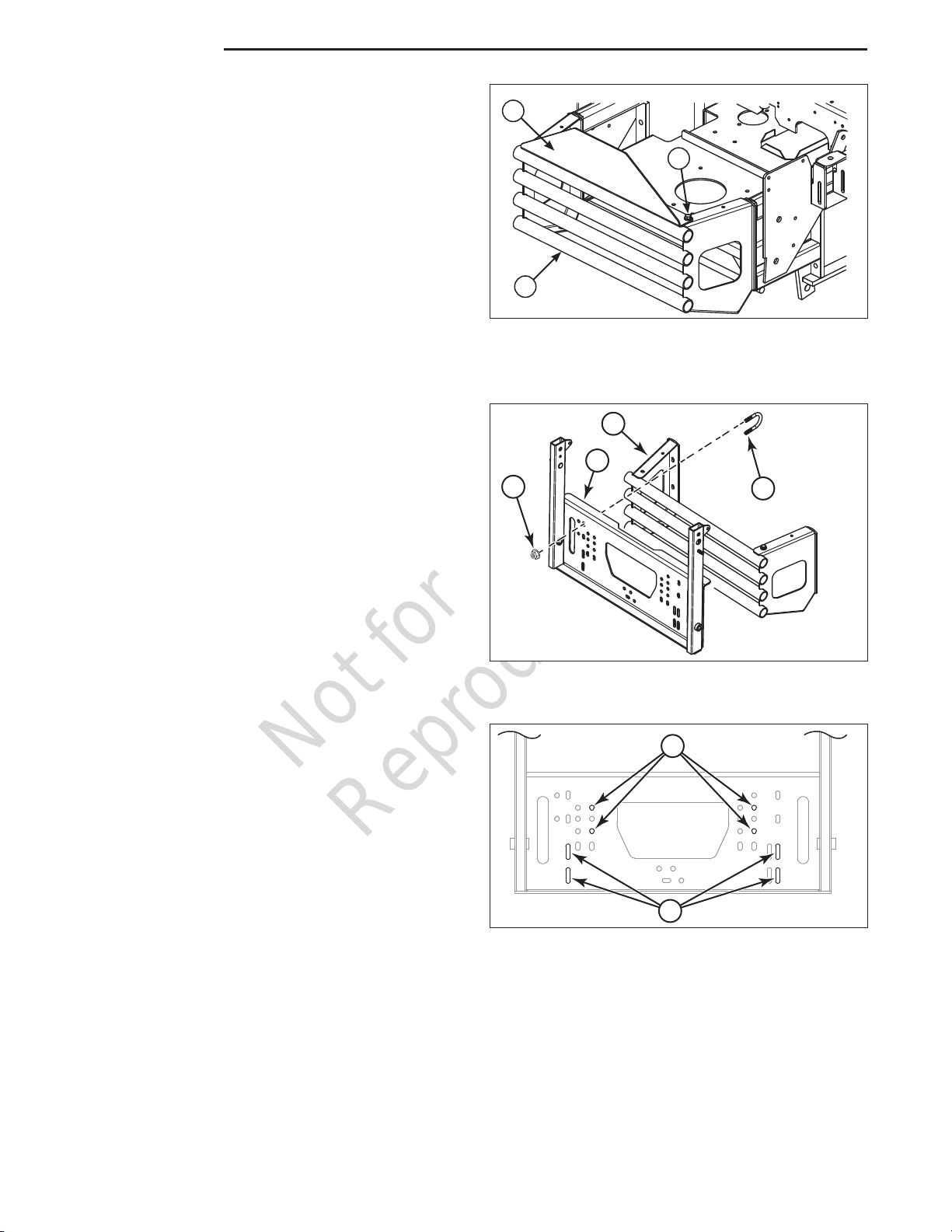
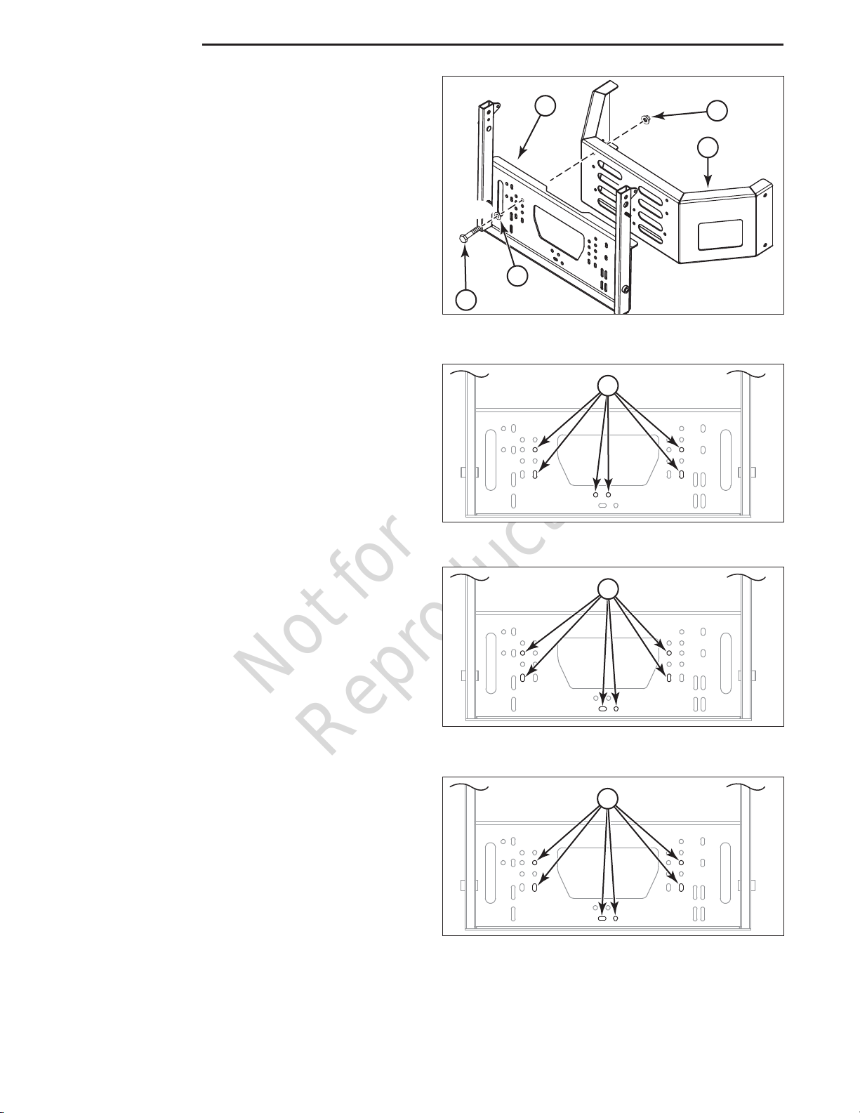
Figure 2. Hopper Mount Components - Round
Tube Bumper
Install the Hopper Mount
All zero-turn riding mowers with mid-mounting mower
decks that this hopper collection system fits use
the same hopper mount but use different hardware
and mounting holes to mount it. Please refer to
the following instructions and figures for the proper
mounting holes and hardware for mounting the hopper
mount.
Zero-Turn Riding Mowers with Round Tube
Bumpers
Four (4) 3/8 U-bolts (A, Figure 2) and eight (8) 3/8-16
nylock flange nuts (B) are used to mount the hopper
mount (C) to the round tube bumper (D).
A
B
Figure 3. Hopper Mount Position - IS2100Z w/ 52”
Mower Deck (12 cu. ft. Hopper)
IS2100Z with a 52” Mower Deck (12 cu. ft. Hopper)
1. Position the hopper mount onto the bumper and
install two (2) U-bolts over the top bumper tube
and through the holes indicated as “A” in Figure 3
and secure with nylock flange nuts.
2. Install two (2) U-bolts over the middle bumper tube
and through the holes indicated as “B” in Figure 3
and secure with nylock flange nuts.
3. Center the hopper mount plate on the bumper and
tighten the hardware.
4x
8x
A
BC
D
Not for
Reproduction
5
Installation
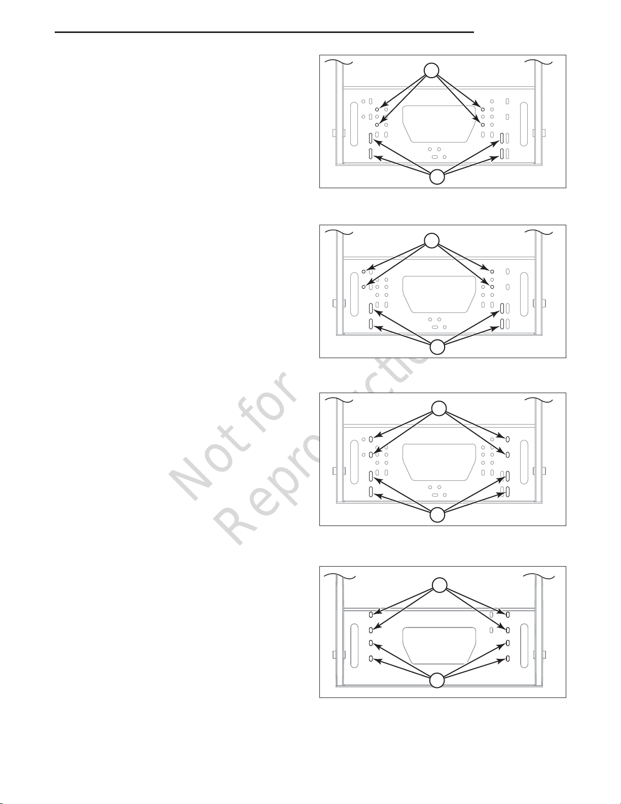
IS2100Z with a 61” Mower Deck (12 cu. ft. Hopper)
1. Position the hopper mount onto the bumper and
install two (2) U-bolts over the top bumper tube
and through the holes indicated as “A” in Figure 4
and secure with nylock flange nuts.
2. Install two (2) U-bolts over the middle bumper tube
and through the holes indicated as “B” in Figure 4
and secure with nylock flange nuts.
3. Slide the hopper mount as far as it will go towards
the discharge side of the mower deck and tighten
the hardware.
A
B
Figure 4. Hopper Mount Position - IS2100Z w/ 61”
Mower Deck (12 cu. ft. Hopper)
IS3100Z with a 61” Mower Deck (12 cu. ft. Hopper)
1. Position the hopper mount onto the bumper and
install two (2) U-bolts over the top bumper tube
and through the holes indicated as “A” in Figure 5
and secure with nylock flange nuts.
2. Install two (2) U-bolts over the third bumper tube
and through the holes indicated as “B” in Figure 5
and secure with nylock flange nuts.
3. Slide the hopper mount as far as it will go towards
the discharge side of the mower deck and tighten
the hardware.
A
B
Figure 5. Hopper Mount Position - IS3100Z w/ 61”
Mower Deck (12 cu. ft. Hopper)
A
B
Figure 6. Hopper Mount Position - IS3100Z w/ 61”
Mower Deck (14 cu. ft. Hopper)
IS3100Z with a 61” Mower Deck (14 cu. ft. Hopper)
1. Position the hopper mount onto the bumper and
install two (2) U-bolts over the top bumper tube
and through the holes indicated as “A” in Figure 6
and secure with nylock flange nuts.
2. Install two (2) U-bolts over the third bumper tube
and through the holes indicated as “B” in Figure 6
and secure with nylock flange nuts.
3. Center the hopper mount plate on the bumper and
tighten the hardware.
A
B
IS3200Z with a 61” Mower Deck (14 cu. ft. Hopper)
1. Position the hopper mount onto the bumper and
install two (2) U-bolts over the top bumper tube
and through the holes indicated as “A” in Figure 7
and secure with nylock flange nuts.
2. Install two (2) U-bolts over the second bumper
tube and through the holes indicated as “B” in
Figure 7 and secure with nylock flange nuts.
3. Center the hopper mount plate on the bumper and
tighten the hardware.
Figure 7. Hopper Mount Position - IS3200Z w/61”
Mower Deck (14 cu. ft. Hopper)
Not for
Reproduction
6www.ferrisindustries.com | www.snapperpro.com
Installation
Figure 8. Install the Hopper Mount (S200XT
Models)
Zero-Turn Riding Mowers with Flat Plate Bumpers
Six (6) 3/8-16 X 1” bolts (A, Figure 8), 3/8 SAE
washers (B) and 3/8-16 nylock flange nuts (C) are
used to mount the hopper mount (D) to the round tube
bumper (E).
S150XT with a 52” Mower Deck (12 cu. ft. Hopper)
1. Position the hopper mount onto the bumper
and install six (6) 3/8-16 X 1” bolts and 3/8 SAE
washers through the holes in the hopper mount
indicated as “A” in Figure 9, and the pre-drilled
holes in the bumper and secure with six (6) nylock
flange nuts.
A
Figure 9. Hopper Mount Position - S150XT w/ 52”
Mower Deck (12 cu. ft. Hopper)
S200XT with a 61” Mower Deck (12 cu. ft. Hopper)
1. Position the hopper mount onto the bumper
and install six (6) 3/8-16 X 1” bolts and 3/8 SAE
washers through the holes in the hopper mount
indicated as “A” in Figure 10, and the pre-drilled
holes in the bumper and secure with six (6) nylock
flange nuts.
S200XT with a 61” Mower Deck (14 cu. ft. Hopper)
1. Position the hopper mount onto the bumper
and install six (6) 3/8-16 X 1” bolts and 3/8 SAE
washers through the holes in the hopper mount
indicated as “A” in Figure 11, and the pre-drilled
holes in the bumper and secure with six (6) nylock
flange nuts.
A
A
Figure 10. Hopper Mount Position - S200XT w/ 61”
Mower Deck (12 cu. ft. Hopper)
Figure 11. Hopper Mount Position - S200XT w/ 61”
Mower Deck (14 cu. ft. Hopper)
D
E
C
B
A
6x
6x
Not for
Reproduction
7
Installation
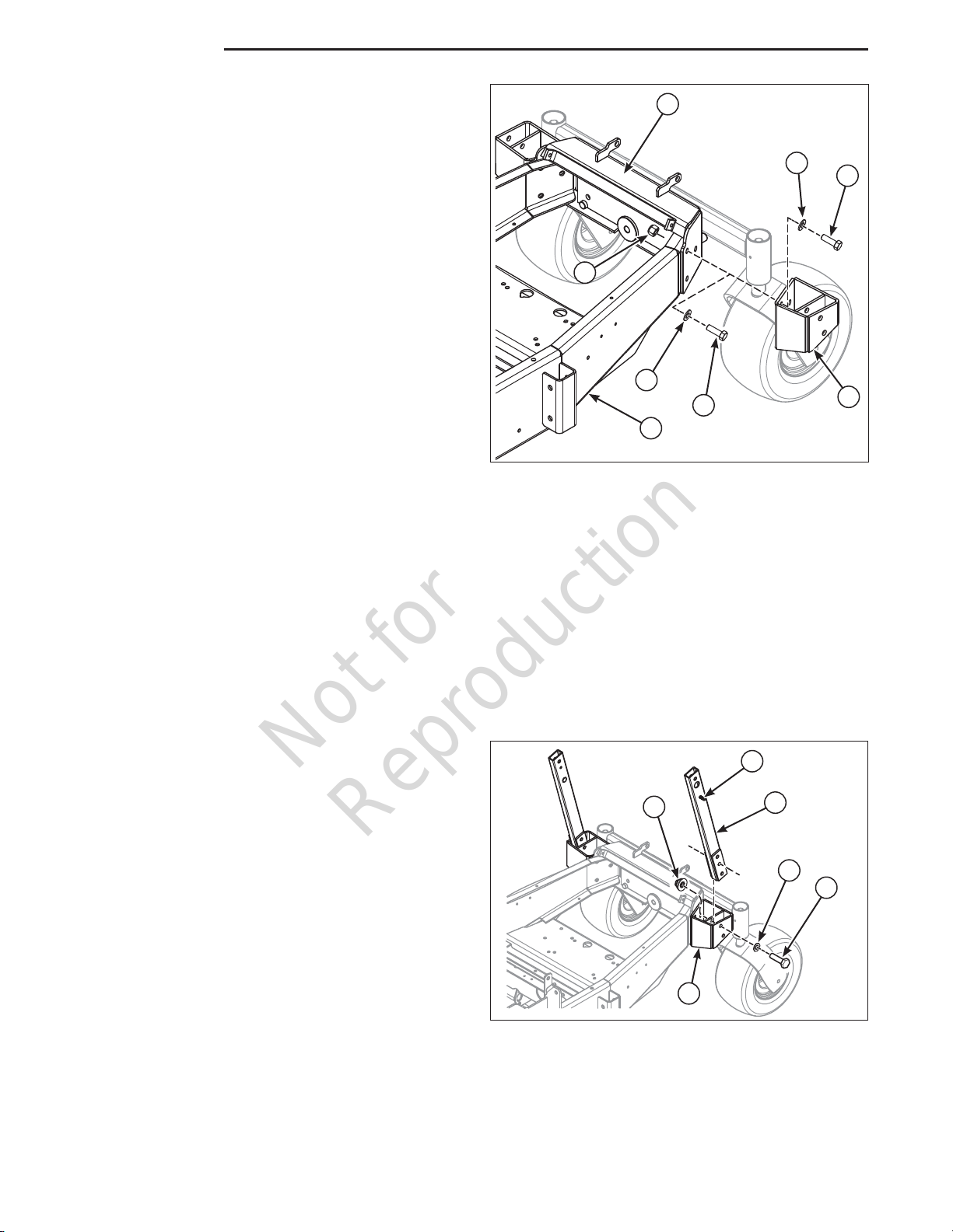
Install the Stabilizer Strap (S150XT and
S200XT Units Equipped with Kawasaki or
Briggs & Stratton Engines)
1. Using a 3/8 X 1-1/4” bolt (A, Figure 12), 3/8 SAE
washer (B) and 3/8 nylock flange nut (C) to mount
the stabilizer strap (D) to the hopper mount (E).
2. Remove the lower bolt in the gas tank mount
bracket (F).
3. Secure the bottom of the stabilizer strap to the
lower gas tank mount hole and unit’s frame using
a 3/8 X 1-1/2” (G), 3/8 SAE washer and 3/8 nylock
flange nut.
4. Repeat this process for the other side of the unit.
Install the Stabilizer Strap and Extension
Plate (S200XT Units Equipped with Kohler
Engines)
1. Loosely install a 3/8 X 1-1/4” bolt (A, Figure 13),
3/8 SAE washer (B) and 3/8 nylock flange nut
(C) to mount the stabilizer strap (D) to the hopper
mount (E).
2. Remove the lower bolt in the gas tank mount
bracket (F).
3. Route a 3/8 X 1-3/4” bolt (G), a 3/8 SAE washer
through the lower hole in the gas tank mount
bracket, the frame of the unit, the spacer (H), the
extension plate (I) and loosely install a 3/8 nylock
flange nut.
4. Mount the bottom of the stabilizer strap to the
extension plate by loosely installing a 3/8 X 1-1/4”
bolt and 3/8 nylock flange nut.
5. Tighten all three nuts.
6. Repeat the process for the other side of the unit.
DC
C
A
B
F
B
G
Figure 12. Install the Stabilizer Strap (S200XT
Units Only)
E
G
E
CD
BA
B
C
H
I
CF
Figure 13. Installing the Stabilizer Strap and
Extension Plate (S200XT Models equipped with
Kohler Engine Only)
Not for
Reproduction
8www.ferrisindustries.com | www.snapperpro.com
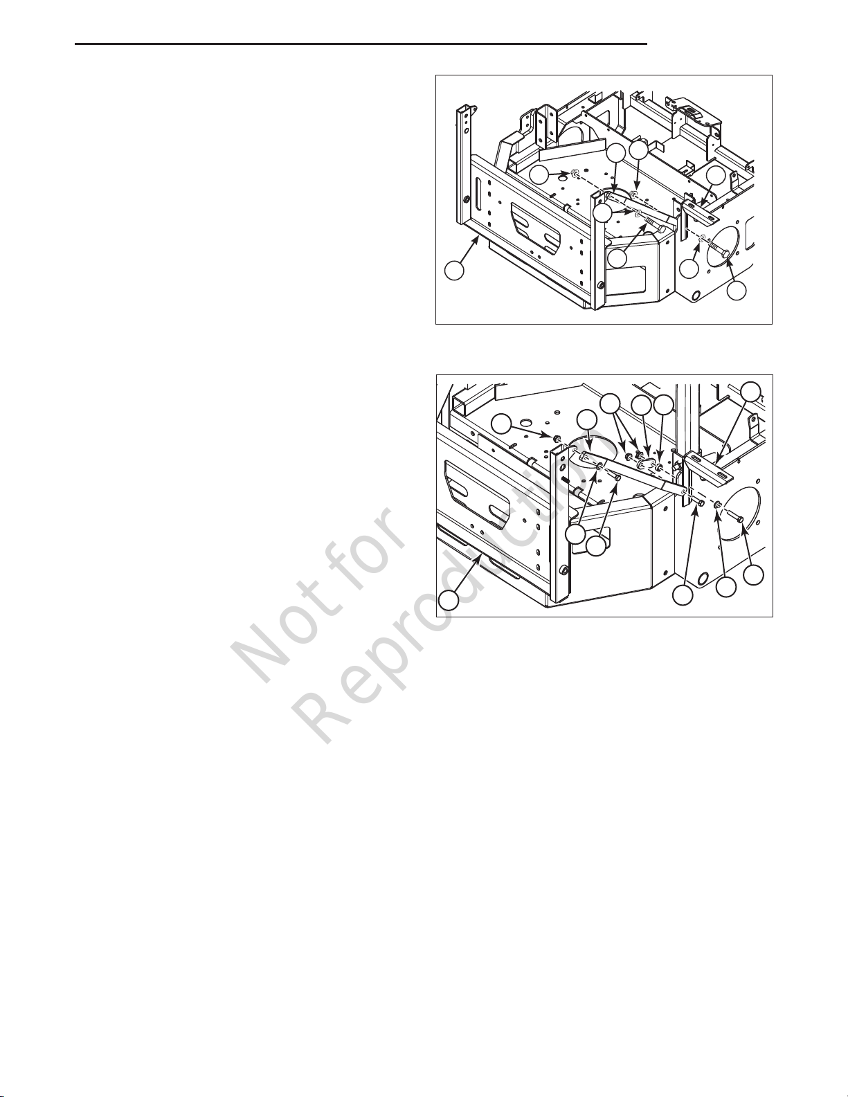
Install the Hopper Mount Brackets (S800X
Models)
1. Chock the wheels of the unit to prevent movement.
Left Side of the Unit
2. Place a bottle or floor jack underneath the left
side of the frame of the machine (A, Figure 14)
and carefully raise the unit until the pressure is
removed from the tail wheel mount (B).
3. Place blocking underneath the tail wheel mount.
4. Remove the three (3) 1/2 bolts (C), 1/2 washers
(D) and 1/2 nylon lock nuts (E) that secure left
side of the tail wheel mount to the frame of the
machine.
5. Using three (3) 1/2” X 1-1/2” bolts (F), 1/2 washers
and 1/2 nylon lock nuts and secure the hopper
mount brackets (G) to the left side of the tail wheel
mount and the frame of the machine.
Right Side of the Unit
2. Place a bottle or floor jack underneath the right
side of the frame of the machine (A, Figure 14)
and carefully raise the unit until the pressure is
removed from the tail wheel mount (B).
3. Place blocking underneath the tail wheel mount.
4. Remove the three (3) 1/2 bolts (C), 1/2 washers
(D) and 1/2 nylon lock nuts (E) that secure the
right side of the tail wheel mount to the frame of
the machine.
5. Using three (3) 1/2” X 1-1/2” bolts (F), 1/2 washers
and 1/2 nylon lock nuts and secure the hopper
mount brackets (G) to the right side of the tail
wheel mount and the frame of the machine.
A
DF
C
D
E
B
G
Figure 14. Install the Support Plate Frame
Brackets (S800X Models)
Install the Hopper Mount Arms (S800X
Models)
1. Install the hopper mount arm (A, Figure 15) into
the hopper mount bracket (B) with the mount pins
(C) facing towards the outside of the machine and
secure in place with two (2)1/2 X 2-3/4 bolts (D),
1/2 washer (E) and 1/2 nylock flange nut (F).
2. Repeat the process for the other side of the unit.
Figure 15. Install the Hopper Mount Arms
A
B
F
ED
C
Installation
Not for
Reproduction
9
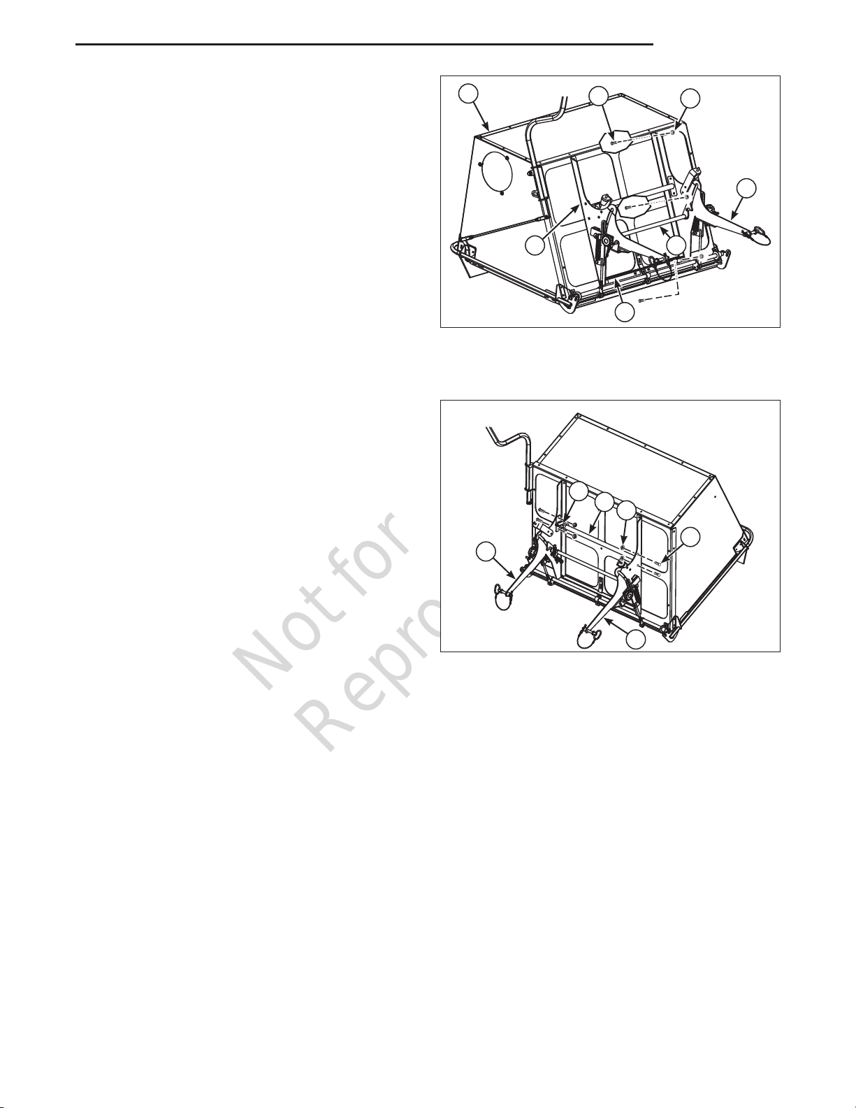
Attach the Support Plates to the Hopper
Assembly
There is a left (A, Figure 16) and right support plate
(B). Use the illustration to help identify which side is
which. With the support plates installed properly the
mounting tabs should be pointing toward the center of
the hopper. The right side also has an additional slot
which is used for the spring anchor bolt.
1. Position the support plates on the hopper as
shown in Figure 16. The bottom of the support
plates need to be slid behind the tabs on the
support weldment (C)
2. Attach the left support (A) to the hopper assembly
(D) and secure in place using three (3) 5/16 X 1”
carriage bolts (E) and 5/16 nylock flange nuts (F).
3. Install the center latch assembly (G) into the left
and right support as shown in Figure 16.
3. Attach the right support (B) to the hopper
assembly and secure in place using three (3) 5/16
X 1” carriage bolts and 5/16 nylock flange nuts.
Install the Torsion Tube
1. Position the torsion tube (A, Figure 17) between
the left (B) and right support plates (C). The
spring bracket (D) should be positioned by the
right support plates.
2. Secure the torsion tube in place using four (4) 5/16
X 3/4” bolts (E) and 5/16” nylock flange nuts (F).
A
E
DF
B
Figure 16. Attach the Support Plates to the Hopper
Assembly
C
Figure 17. Install the Torsion Tube
F
A
E
C
B
D
G
Installation
Not for
Reproduction
10 www.ferrisindustries.com | www.snapperpro.com
Installation
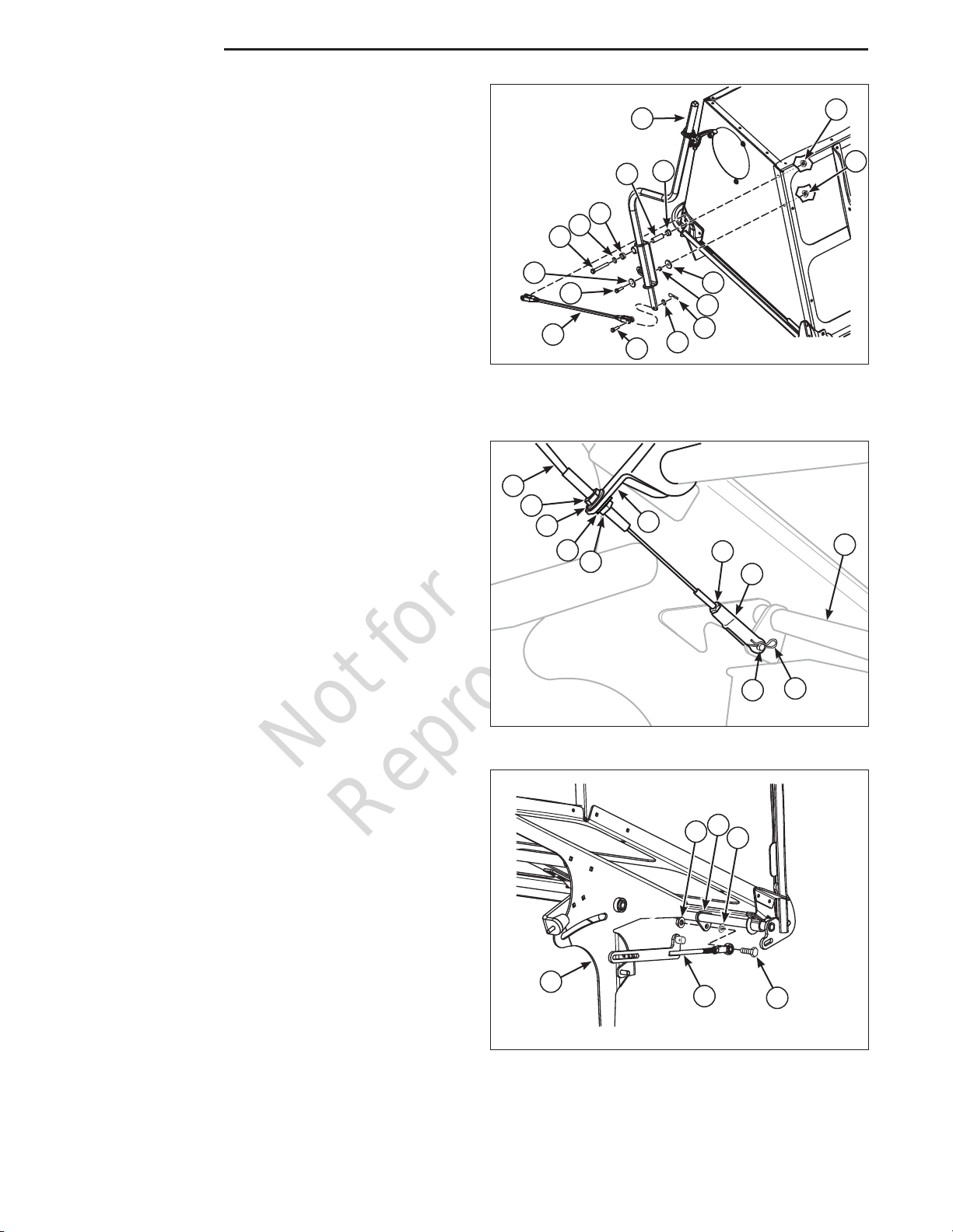
Install the Handle and Control Rod
1. Route a 5/16 X 1” bolt (A, Figure 18) through a
.34 X 1.25 X 10 ga. washer (B), the handle (C)
the .328 X .497 X .218 long spacer (D), another
washer, the hopper and secure with a 5/16 nylock
flange nut (E).
2. Press the two bushings (F) into the handle
assembly.
3. Route a 3/8 X 2-3/4 bolt (G), a 3/8 SAE washer
(H) through the handle, a .39 X .625 X 1.85 spacer
(I), the hopper and secure with a 3/8 nylock flange
nut (M).
4. Install the door latch rod (J) on to the hopper and
the handle and secure both ends using a 3/8”
clevis pin (K), 3/8 SAE washer and secure using a
1/8 X 3/4” cotter pin (L). Figure 18. Install the Handle and Control Rod
(Cable not shown for illustration purposes only)
A
GHF
JKL
H
CM
F
I
B
D
B
Connecting the Cable
1. Route the cable (A, Figure 19) from the handle to
the center latch assembly (B).
2. Route the cable through the bracket on the torsion
tube (C) and loosely install the jam nuts (D) and
washers (E) on either side of the bracket.
3. Install the jam nut (F) and the clevis (G) on the
cable. Tighten the jam nut on the clevis.
4. Install the clevis on the center latch assembly and
secure with clevis pin (H) and cotter pin (I).
Figure 19. Connecting the Cable
ADE
EFG
HI
B
D
C
Installing the Latch Bars
1. Position the left latch bar assembly (A, Figure 20)
into the left support plate (B) as shown in Figure 9.
2. Route a 3/8 X 1-1/2” bolt (C), through the eyebolt
of the latch bar assembly, a 3/8 washer (D), gate
latch assembly tab (E), and secure with a 3/8
nylock flange nut (F).
3. Repeat this process for the other side of the unit.
Figure 20. Installing the Latch Bars (Left side
shown)
A
BC
FD
E
E
Questo manuale è adatto per i seguenti modelli
1
Indice
Altri manuali Ferris Accessori per tosaerba

Ferris
Ferris 1846197 Manuale utente

Ferris
Ferris 45494KIT Manuale utente

Ferris
Ferris 5600056 Manuale utente

Ferris
Ferris SNAPPER PRO FAST-Vac 61 Manuale utente

Ferris
Ferris IS1500Z Series Manuale

Ferris
Ferris 5600366 Manuale utente

Ferris
Ferris SNAPPER PRO IS500Z Manuale

Ferris
Ferris 5049751 Manuale utente

Ferris
Ferris 48550 Manuale utente


