Fireboy- Xintex FBD-MZ Istruzioni originali

1
Part Number 18166, G, 01/11/2022
FBD-MZ
Fire Detection System
Fire Detection System, Multi-Zone
Owner’s Manual
&
Installation Instructions
Read and comply with all instructions, warnings and limitations before
installing, servicing or removing this device.
Additional copies of this manual are available at no charge by contacting the manufacturer,
distributor or dealer. Fireboy-Xintex reserves the right to change features without notice.

2
Part Number 18166, G, 01/11/2022
Specifications
3
Operation of the FBD-MZ Fire Detection System
3
Installation
4
Installing the Display
4
Installing Detectors and other Devices on Detection Circuits
5
Field Wiring to Detectors
5
Electrical Connections
5
Control Module Troubleshooting LEDs
10
Programming the Display
10
Changing the Brightness and Contrast of the Display
10
Changing the Number of Zones
11
Enabling the Screensaver
13
Changing the Zone Text
14
Mute Function
15
Reset Function
15
Testing the FBD-MZ Fire Detection System
16
Maintenance
16
In the Event of an Alarm
16
Repairing the FBD-MZ Fire Detection System
16
Returning the FBD-MZ Fire Detection System
16
1 Year Limited Warranty
17

3
Part Number 18166, G, 01/11/2022
Specifications
System Specifications
Operating Voltage: 9-32V DC
Quiescent Current Draw: 200mA @ 12V DC, 100mA @ 24V DC, 240mA @ 32V DC
Alarm Current Draw: 220mA @ 12V DC, 115mA @ 24V DC, 260mA @ 32V DC
Operating/Storage Temperature: 22°F (-6°C) to 158°F (70°C)
Relay Output: 500mA
Display Dimensions: 2.6” (67mm) x 2.6” (67mm) x 2.0” (51mm)
Control Module Dimensions: 7.29” (186mm) x 5.49” (140mm) x 1.39” (36mm)
NOTE
ABOVE CURRENT DRAWS PERTAIN ONLY TO THE DISPLAY AND MODULE UNIT. FULL SYSTEM
CURRENT DRAWS MUST ALSO ACCOUNT FOR EACH DETECTOR USED IN THE SYSTEM.
Operation of the FBD-MZ Fire Detection System
The FBD-MZ Detection System allows the monitoring of 4-12 zones of smoke and heat detectors.
Eight (8) detectors may be installed on each zone of the system. The system will monitor and
report an alarm both visually and audibly. The system also has 2 additional dry contact relay
outputs that can be used for additional notification.
4
Part Number 18166, G, 01/11/2022
Installation
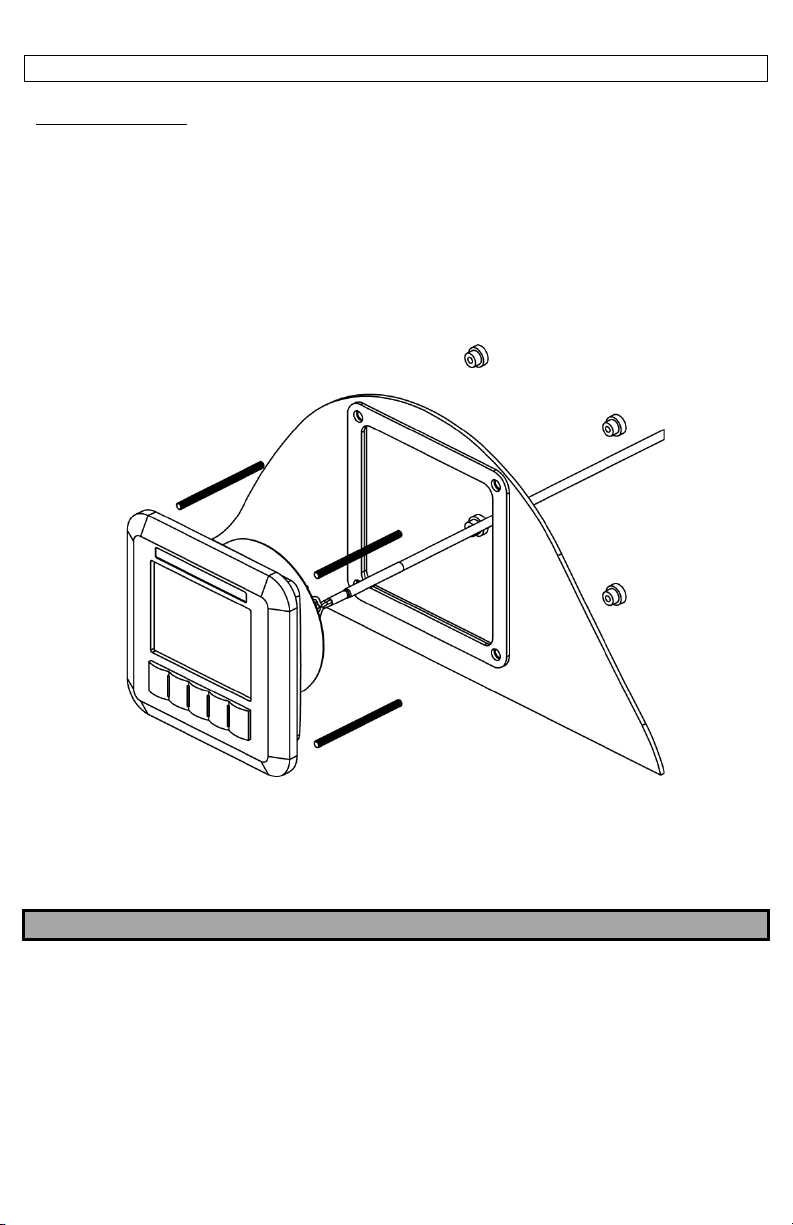
Installing the Display
Locate the Display so that it may be easily observed while the vessel is underway.
The Display may be mounted into a bulkhead, dash, or panel. Leave enough clearance behind the
Display for the cable connections. A paper template is provided with the Display to locate the
holes required to mount the Display. It is recommended to verify the measurements after
marking the locations. Drill out the mounting holes and cut out the area needed to insert the
Display. Thread the provided M4 studs into the rear of the Display. Install the Display and secure
with the provided nuts from the back side of the bulkhead, dash, or panel.
Locate the Control Module somewhere near the Display. It is not necessary to mount the Control
Module where it can be seen at all times, however, it must be protected from the elements. Use
the provided #8 Screws to secure the Control Module once the mounting holes are drilled.
NOTE
DO NOT MAKE ELECTRICAL CONNECTIONS AT THIS TIME. THEY WILL BE ADDRESSED IN A LATER
SECTION.
5
Part Number 18166, G, 01/11/2022
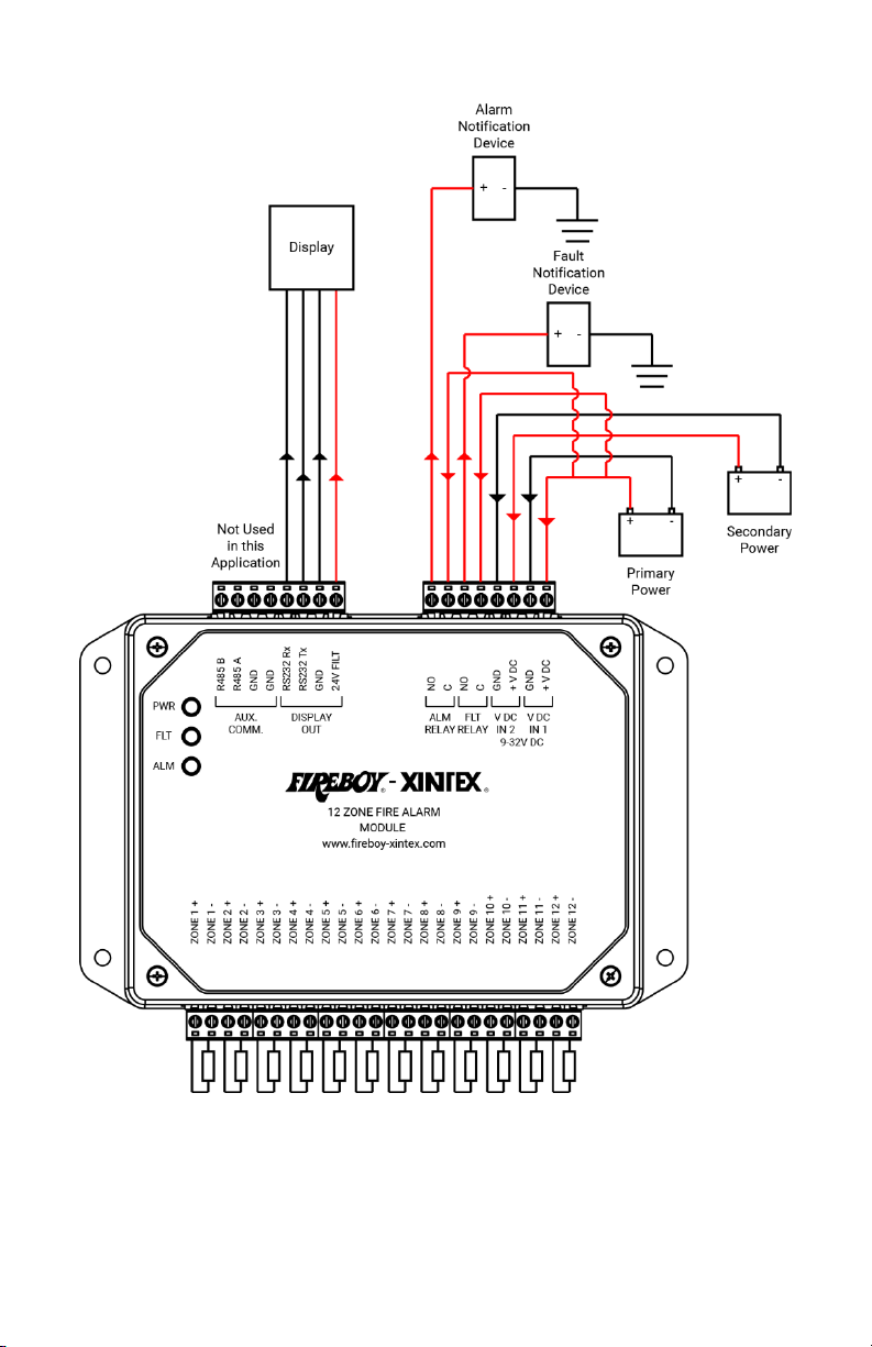
Installing Detectors and other Devices on Detection Circuits
Locate and install the heat/smoke detectors or other devices by following the manufacturer’s
instructions.
Field Wiring
Suitable 12-18 AWG cable should be used for all field wiring, per the NFPA or other International
standards. Secure the field wiring with the appropriate hardware for the application, per local
codes. Take care not to pinch, break, or cut the field wiring while routing. The field wiring should
be routed starting at the Module, then to the pre-determined location of the first Heat/Smoke
Detector or Relay Operated Device on the circuit. Connect to the Control Module using the screw
terminal connectors provided. Connect to each component by following the Manufacturer’s
instructions. Repeat the routing process to each additional component on the circuit. Connect
the provided 4.7K ohm End of Line Resistor to the last component on the circuit by following the
Manufacturer’s instructions. Connect the provided 4.7K ohm End of Line Resistor to the Module
whenever a Zone is not used.
Devices that utilize the dry contact relays must be installed using the Common (C) and Normally
Open (NO) contacts.
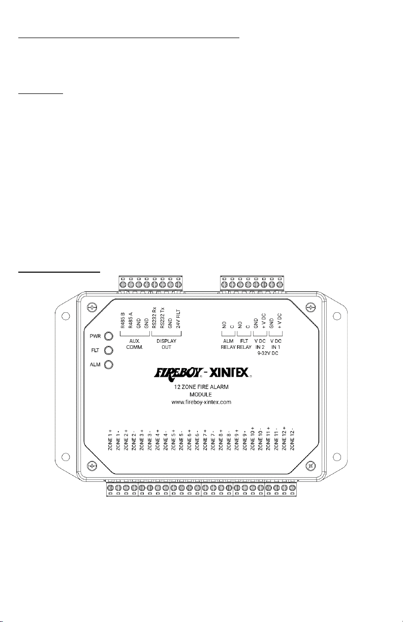
Electrical Connections
Connect the main input voltage (9-32V DC) to the Control Module terminals labeled “V DC IN 1”.
Connect the backup power source to the Control Module terminals labeled “V DC IN 2”.

6
Part Number 18166, G, 01/11/2022
Electrical Connections Continued
Connect the Display to the Control Module terminals labeled “Display OUT”.
NOTE
IF THE HARNESS MUST BE DISASSEMBLED TO FEED THROUGH A HOLE IN A SURFACE, DISCONNECT
THE GREEN CONNECTOR ONLY. RECONNECT THE HARNESS AS FOLLOWS.
Connect Notification Devices to the Control Module terminals labeled “ALM RELAY” for
notification when the system in an alarm state.
Connect Notification Devices to the Control Module terminals labeled “FLT RELAY” for notification
when the system in a fault state.
“AUX. COMM.” connections are not used in this application.
Connect the Heat/Smoke Detectors and other input devices to the Control Module terminals
labeled “ZONE # +” and “ZONE # –“.
Terminal
Wire Color
1
Red
2
Black
3
Green
4
White
5
N/A
6
N/A
7
N/A
8
N/A
7
Part Number 18166, G, 01/11/2022
Typical Wiring Example
8
Part Number 18166, G, 01/11/2022
Electrical Connections Continued
Typical Zone Wiring Examples

9
Part Number 18166, G, 01/11/2022
Component Wiring Examples
Smoke/Heat Detector
Pull Station/Call Point
Relay Connection
Linear Heat Cable
NO
C
NC
From FACP
or
Previous Device
EOL Resistor
+
-
EOL Resistor
From FACP
or
Previous Device
To
Next
Device
or
+
-
+
-
EOL Resistor
From FACP
or
Previous Device
To
Next
Device
or
+
-
+
-
+
-
Linear Heat Cable
EOL Resistor
From FACP
or
Previous Device
10
Part Number 18166, G, 01/11/2022
Control Module Troubleshooting LEDs
When powered, the upper Control Module LED will flash Green. In the event of a Fault, the center
Control Module LED will illuminate an Amber color until the issue is corrected. In the event of an
Alarm, the lower Control Module LED will illuminate a Red color until the alarm condition is over
and the system is reset.
Programming the Display
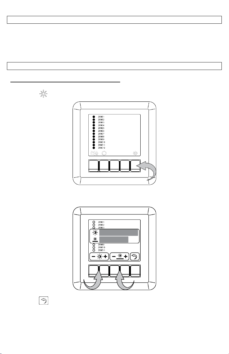
Changing the Brightness and Contrast of the Display
Press the “ ” button.
The Brightness and Contrast settings will be displayed over the current screen. Use the buttons
beneath each setting to adjust the corresponding setting.
Press the “ ” button to exit the menu once you have finished to exit.
Indice
Altri manuali Fireboy- Xintex Allarme antincendio


