fisair DFLEX Series Manuale utente

FISAIR S.L. C/Uranio, 20; PoI. Ind. Aimayr, 28330 San Martín de la Vega (Madrid) España.
Tel: (+34) 91 692 15 14 Fax: (+34) 91 691 64 56 | info@fisair.com| fisair.com
ASSEMBLY INSTRUCTIONS
DFLEX SERIES
IMSX-EN-21-0
In compliance with the European Union regulations on the Safety of Machines,
you must read these instructions carefully before installing the equipment.

DFLEX Assembly instructions |
2

DFLEX Assembly instructions |
3
Contents
1. Introduction. .......................................................................................4
2. Safety Instructions..............................................................................5
3. Identification of parts ..........................................................................7
4. Location platform................................................................................8
5. Arrangement of modules....................................................................9
5.1 Module 9 arrangement (optional)...................................................................9
5.2 Module 3 arrangement ................................................................................10
5.3 Module 2 arrangement ................................................................................12
5.4 Module 4 arrangement ................................................................................14
5.5 Module 1 arrangement ................................................................................17
5.6 Module 5 arrangement ................................................................................18
5.6.1 Steam reactivation heater ............................................................................21
5.6.2 Electric reactivation heater ..........................................................................24
5.6.3 Gas reactivation heater................................................................................38
5.7 Module 6 arrangement ................................................................................43
5.8 Module 8 arrangement (optional).................................................................44
5.9 Module 7 arrangement ................................................................................45
6. Electrical wiring. ...............................................................................48
7. Connection of the drainage...............................................................50
8. Removing the transport fixing plates from the process fan................52

DFLEX Assembly instructions |
4
1. Introduction.
To ensure the correct operation of your DFLEX dehumidifier, please read this manual
carefully and keep it for future reference.
If there is any part of this document that you do not understand, or if you have any
questions about your dehumidifier, please contact us:
FISAIR, S.L.U.
Tel.: (+34) 91 692 15 14 –Madrid –SPAIN
Fax: (+34) 91 691 64 56 –Madrid –SPAIN
Email address www.info@fisair.com
Or contact your local distributor.
IMPORTANT!
The correctuseof the dehumidifier includesfollowing our instructions for installation, set-
up, operation, and maintenance, as well as following the steps indicated in the
instructions in the correct sequence as described.
This dehumidifier may only be used by persons who are fully qualified and authorized to
do so.
Any person who transports and/or uses the unit or who works with it must read and
understand the relevant section of this manual, in particular the section entitled "Safety
Instructions".
You are advised to keep a copy of the user manual with the dehumidifier (or nearby).
Ignoring these instructions may invalidate all applicable guarantees and warranties.

DFLEX Assembly instructions |
5
2. Safety Instructions.
Please read these safety notes carefully and examine the equipment to become familiar
with it before installing, commissioning or servicing.
The following symbols or messages may appear in this document or on the equipment.
They warn of potential hazards or provide information that may help you clarify or simplify
a procedure.
Attention, Live Current
The presence of this symbol on a hazard or warning label indicates that there
is a risk of electrocution, which can lead to personal injury or death if the
instructions are not followed.
Attention
This is a safety alert symbol. It warns of the potential of bodily injury. Observe
all safety information with this symbol to avoid any situation that could lead to
injuries and/or damage to the unit.

DFLEX Assembly instructions |
6
We recommend that the personnel responsible for the equipment should use these
instructions to familiarize themselves with the goods they will receive and subsequently
assemble.
All operations must be carried out by suitably qualified personnel.
Observe local regulations, especially those protecting personnel from any implicit
hazards during the assembly process.

DFLEX Assembly instructions |
7
3. Identification of parts
-1- Process Filtration module.
-2- Base Unit module.
-3- Process Fan module.
-4- Basic module.
-5- Reactivation battery module.
-6- Reactivation Filtration module.
-7- Reactivation Fan module.
-8- Heat exchanger module (optional).
-9- Absolute Filtration module (optional).
-10- Control Panel.
1
6
5
4
8
7
9
3
10
2

DFLEX Assembly instructions |
8
4. Location platform
Check that the DFLEX platform is properly planned and has the minimum dimensions
indicated.
Refer to dimensions A and B in the DFLEX external dimensions diagram.
If the model incorporates extra batteries, space will be required for the condensate drain,
in which case the height 2H is determined by the expression.:
Where P is the total fan pressure
Provide metric and mechanical tools such as:
- Spanners and socket set 13/17/19/24/32 mm.
- Clamps. >300mm<
- Tape measure. >5m<
- Sealant applicator gun for 300mL cartridges.
- 3-6 mm Allen keys.
Siphon for negative pressures

DFLEX Assembly instructions |
9
5. Arrangement of modules
5.1 Module 9 arrangement (optional)
If module 9 is not available, proceed directly to point 5.2, following the steps in this
section (5.1).
Implementation steps:
- Locate the module labelled -9- (or module -3- if -9- is not available).
- Position it 100mm from the right and front edge of the platform, aligned with the
longitudinal axis of the platform.
- Remove the transport guards.
DFLEX Assembly instructions |
10
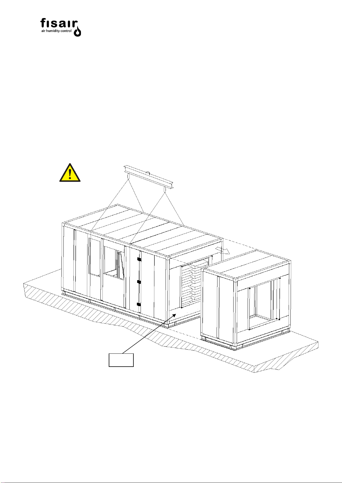
5.2 Module 3 arrangement
Implementation steps:
- Locate module -3-
- Remove the transport guards and unload it at > 600mm in line with module -3-,
and match the section identified as S3-9.
- Inside is the box with gaskets and screws for later assembly according to
instructions.
- Then apply the self-adhesive sealing gasket to the contact edge between
sections, on module -3- face only.
S3-9
Altri manuali per DFLEX Series
2
Questo manuale è adatto per i seguenti modelli
11
Indice
Altri manuali fisair Deumidificatore

fisair
fisair DFRA Series Manuale utente

fisair
fisair DFLEX Series Manuale d'uso e manutenzione

fisair
fisair DFRA Series Manuale d'uso e manutenzione

fisair
fisair DFRA Series Manuale utente

fisair
fisair DFRIGO Series Manuale utente

fisair
fisair DFRA Series Manuale d'uso e manutenzione

fisair
fisair DFLEX Series Manuale utente

fisair
fisair DFRB-060-E Guida all'installazione