
Fly Sky FS-CT6 (A/B) Manuale utente

FlySky FS-CT6 (A/B)
User Manual
for Airplane

Introduction
This manual will not cover helicopter setup as that is covered in the manual
that is included with some versions of the T6, and is available on the
manufacturers website. The information covered in this manual is for both
versions of the T6, the T6A and T6B.
The T6 is manufactured by FlySky and is rebranded for other retailers. It can
be found under the following brands HobbyKing, Exceed RC, Turborix,
Radiolink, etc...
When you unpack your radio depending which brand you have you will find,
1-Transmitter, 1-Receiver, 1-receiver bind plug, 1-USB cable, and 1-mini CD
containing T6config, a manual, and prolific drivers. The prolific drivers are useless
unless you have Win98 or some other outdated OS. If you have WinXP, Vista, or
Win7 you will need to download drivers here. The first driver listed on the linked
page under “T6 drivers” works with all three operating systems listed in the line
above.
Once you have everything unpacked and fresh AA batteries in your
Transmitter (Tx) insert the CD into your drive and install T6onfig to your
computer. Do not install the prolific drivers. Download the drivers from the link
above and store them on your computer. Plug the USB cable included with your
radio into a USB port on your computer. Your computer will start looking for
drivers. It will eventually ask you for the location of the driver. Enter the location
where you stored the downloaded drivers on your computer. After Windows has
finished installing the driver it will be necessary to assign a COM port to the USB
cable. To do this you simply go into “Device Manager” on your computer. Look
under “Ports (COM & LTP)” the USB cable should appear as “Silicon
Labsxxxxxxxx”. To assign a specific COM port to the cable right click on the USB
cable and select “properties”. In the properties window click the “Port Settings tab.
Then click the advanced button. In the next window you will see a “COM Port
Number” button. Click that and select a port between 1 and 6, and click “OK”.
You will now get a warning about other devices not working properly if you
choose a port already assigned to another device. Ignore this warning and
continue. After you have completed this step you may now plug the USB cable
into your Tx.
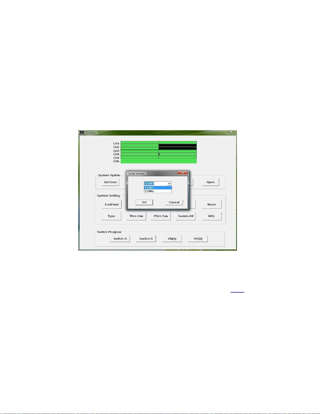
Open T6config, power on your Tx, and select the COM port you assigned to
the USB cable (see illustration 1). Now you should see the channel bars moving as
you manipulate the Tx sticks. If the channel bars do not respond tostick
movement then double check the steps above. If everything is correct, try the
above procedure with a different driver after you uninstall the previous driver.
When the channel bars are responding to the stick movements then proceed to the
next section.
Illustration 1: Selecting the COM port in T6config
Some users suggest at this point you save the “Default Settings”
programmed into the Tx's memory. This step is not necessary unless you want to
use the T6 for helicopters. The default setting are also available here. The default
setting are for a CCPM helicopter.
Tosave the default settings click the “Get User” button. This action
downloads the information stored in the Tx's memory to T6config. Then click
“Save” and select a location where you want to save the data (see illustration 2).
Create a new folder in the location you selected and name it “T6 Settings” and
name the file “Default”, or “Default Settings”. In the “Save” window the “Save”
button is mislabeled. It reads “Open”. Clickit anyway to save your settings.
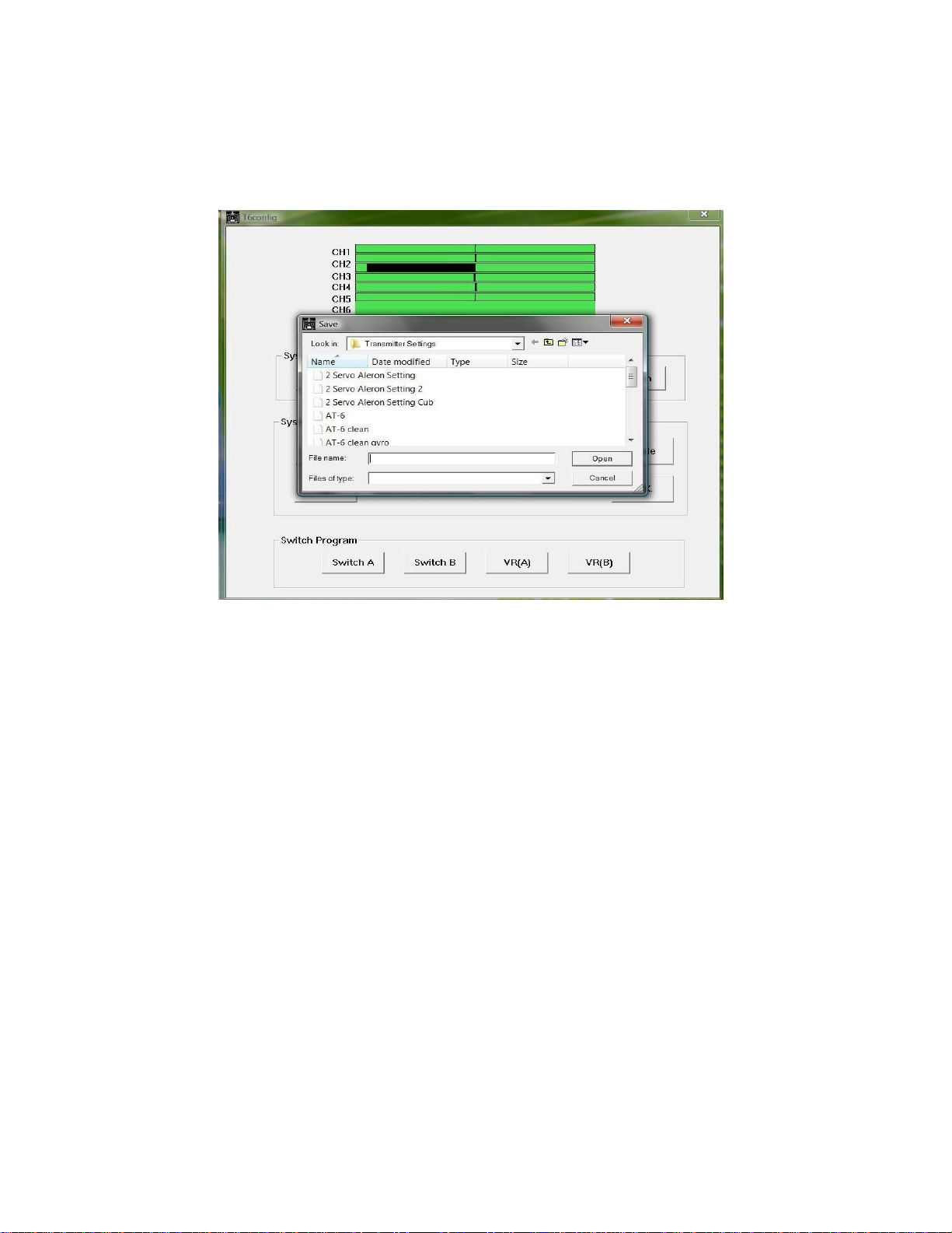
Illustration 2: Saving your settings in T6config
Once you have saved your default setting you can start programming the Tx
for your model. The first step will be to select the Tx mode you will be using. You
have a choice of Mode 1, Mode 2, Mode 3, and Mode 4 (see illustration 3). You
will make this selection in regards to the geographical region where you reside. In
the USA most users select “Mode 2”. It is important to select the mode most
commonly used in your area.

Illustration 3: T6 Mode Selection window
Illustration 4: Open window

To load a saved model to the T6 click “Open”. In the Open window select
the desired saved model file and click “Open”(see illustration 4). If the Tx is
already connected to T6config the file is automatically uploaded to the Tx.
Illustration 5: Aircraft Type window
To select a model type click “Type”. In the type window (see illustration 5) there
are four choices:
1.
ACRO (airplane)
2.
HELI-120
3.
HELI-90
4.
HELI-140
In this manual only ACRO (airplane) will be used. Select “ACRO” to begin
programming your model.

Controls
The T6 channel arrangementis:
CH 1 ailerons
CH 2 elevator
CH 3 throttle
CH 4 rudder
CH 5 aux
CH 6 aux
The T6 has 2 switches on either side of the carry handle. They are designated
SW. A and SW. B. They can be assigned to different functions. These functions
are:
NULL: Deactivated
DR: Dual Rates
ThroCut: Throttle Cut
They can also be assigned to any of the three mixes. The switches can also be used
to switch a mix on or, off. If you are using the T6 on an electric powered model, I
would suggest you assign one of the switches as “Throttle Cut” for your safety.
The T6 has 2 variable knobs on the left and right sides of the face of the Tx.
These are designated VR(A), and VR(B). They can be assigned to CH 5, or
CH 6 through any of the three mixes.
The Tx has 2 gimbals with trim tabs for fine tuning you model in flight.
There is a “Bind/Range Test” button in the lower left corner. This is used to bind
the receiver (Rx) to your Tx. Topreform a range test. Turn on the Tx and then
power on the model. Step away from the model approximately 30 yds. Press and
hold the “Bind/Range Test” button while an assistant observes operation of the
model. For safety concerns do not activate the throttle while range testing.
Other than the “On/Off” switch the Tx has a tricolor LED. The LED shows
green for fully charged batteries, yellow for slightly discharged batteries, and red
for discharged batteries. Fly your model with caution when the LED shows
yellow, and never fly you model when the LED shows red.

Programming
Mixes
Toprogram a mix click the “MIX” button. A small window will open (see
illustration 6). The parameters for mixing are:
1.
Mix Number: MIX 1, MIX 2, and MIX 3
2.
Source: CH 1- CH 6, VR A, and VRB
3.
Des (destination): CH 1- CH6
4. Up Rate: -100% to+100%
5. Down Rate: -100% to +100%
6. Switch: SW A, SW B, ON, and OFF
In the switch parameter do not confuse ON (mix active) and OFF (mix inactive)
with the functions of SW A or SW B. To assign a function for SW A or SW B
select them in “Switch Program”
Illustration 6: Program Mix window

End Point
Toprogram end points click the “End Point” button. A small window will
open that will allow adjustment of the channel end points (see illustration 7).
These can be adjusted from
0-120%. This can be useful when you need extra travel of the servos.
Illustration 7: End Point window
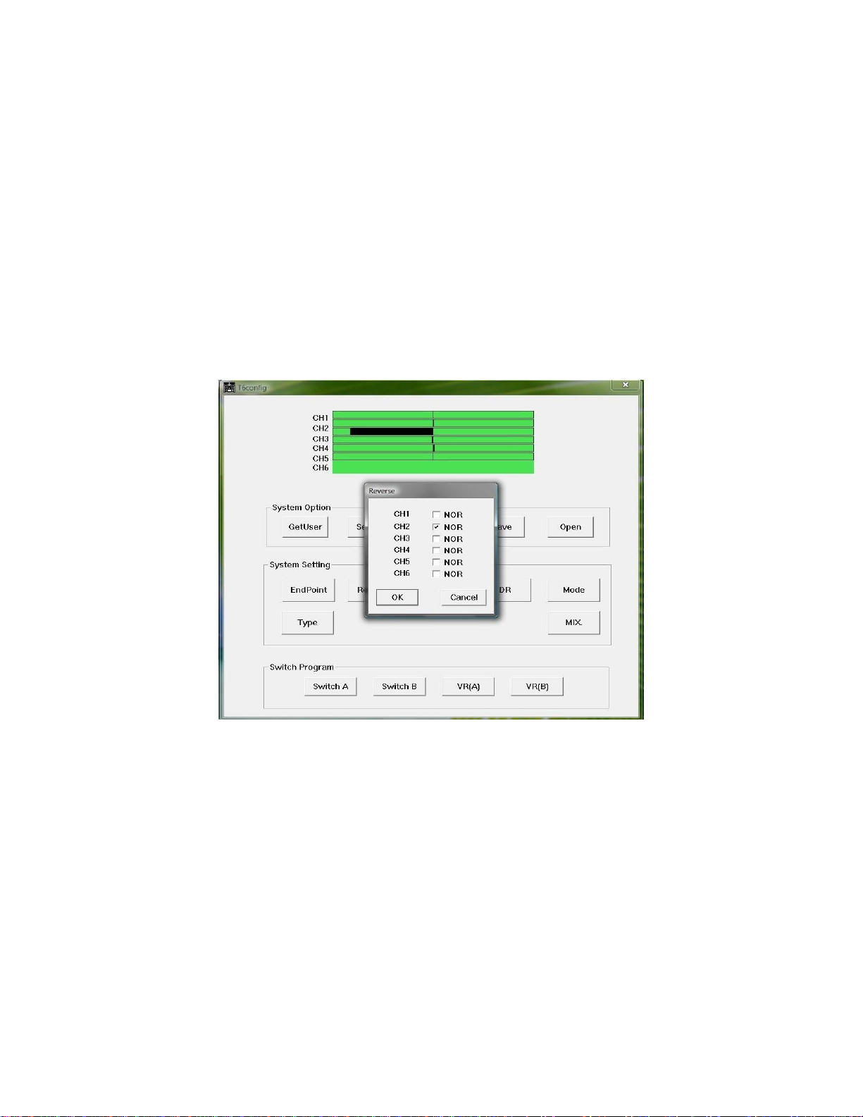
Reverse
To Program servo reversing click the “Reverse” button. In the reverse
window reversing for each channel is performed by placing a check on the channel
that needs to be reversed (see illustration 8).
Illustration 8: Reverse window
Questo manuale è adatto per i seguenti modelli
3
Indice


