Fogo & Chama FIRECRACKER Manuale utente

FIRECRACKER
3 BURNER GAS BARBECUE
INSTRUCTION MANUAL |
Instruction Manual

- 1 -
Instruction Manual
TECHNICAL SPECIFICATIONS
Brand Fogo & Chama
Model
Heat Input (Hs) (kW)
Equipment Category
Gas Reference
Main Burner
Ignition
Destination Countries
SK
Please read the instructions before using the appliance.
WARNING: There are accessible parts that can become very hot. Keep children away from these while in use.
Turn o the gas supply at the gas cylinder after use.
The appliance must not be modied in any way.
Warning! Do not use petrol to light or re-light the grill.
Made in China
Imported by: Fogo & Chama Ltd, 1386 London Road, Leigh-on-Sea, Essex, SS9 2UJ, UK

- 2 -
Instruction Manual
PARTS LIST
- 19 -
PARTS LIST
GB
3
English
PARTS LIST
1 Warming rack 1 11 1
Back left leg
2 Cooking grid 2 12 Side panel
Right top panel
2
3 Flame tamer 3 13 Door cross beam 1
4 Grill body 1 14 Back panel 1
21 2
22 Wheel cover
Wheel
2
23 Gas regulator 1
24 Gas hose 1
5 Side table 2 15 Left door 1
6 1
7 Front left leg 1
16 Right door 1
8 Back right leg 1
17 1
9 1
18 1
10 Left top panel 1
Front right leg
Magnet
Bottom shelf
19 1Cross beam
20 1Wheel axle
24
23
1
2
3
4
5
6
8
22
21
10
12
7
13
9
11
20
14
15
17
18
19
16
1 Warming rack
2 Cooking grid
3 Flame tamer
4 Grill body
5 Side table
6 Back left leg
7 Front left leg
10 Left top panel
12 Side panel
13 Door cross beam
14 Back panel
15 Left door
17 Magnet
18 Bottom shelf
19 Cross beam
11 Right top panel
16 Right door
8 Back right leg
9 Front right leg
20 Wheel axle
22 Wheel cover
23 Gas regulator
24 Gas hose
21 Wheel
D_01561_GJD301-01.indd 19D_01561_GJD301-01.indd 19 07.10.20 20:0507.10.20 20:05
Wheel (2)
2Cooking grid (2) Side panel (2) 22 Wheel cover (2)
4 24
5
6
9
24
23
21
22
20
19
18
17
16
8
11
9
15
12
7
10
6
5
14
13
4
3
2
1

- 3 -
Instruction Manual
PARTS LIST
A M4 x 8mm
x2
B
M6 x 10mm
x54
C
Washer x2
D
Spring washer
x2
Please make sure that your grill is assembled properly. Detailed assembly instructions are
provided in the packaging of each grill, containing specic assembly procedures for each
model. Follow these instructions carefully to ensure that your grill is assembled correctly
and safely.
CAUTION
While we take every eort to ensure that the assembly process is as easy as
possible, it cannot be avoided that fabricated steel parts may have sharp corners
and edges. These can cause cuts if handled without the appropriate level of
care during assembly. Please be careful when handling any parts. We strongly
recommend wearing protective work gloves.
REQUIRED TOOLS, NOT INCLUDED

- 4 -
Instruction Manual
- 21 -
5
English
ASSAMBLY
1
2
Bx 12M6 x 10mm
Assambly
6
B
C
D
9
19
202122
18
8
7
Cx 2Washer
Dx 2R pin
ASSEMBLY
Washer
Spring shim
GB
D_01561_GJD301-01.indd 21D_01561_GJD301-01.indd 21 07.10.20 20:0507.10.20 20:05
ASSEMBLY
6
7
19
18
9
8
x 12M6 x 10mmB
22 21 20
C
D
x 2
x 2
B
D
C

- 5 -
Instruction Manual
- 22 -
6
Assambly
A M4 x 8mm x 2
Bx 4M6 x 10mm
3
4
Bx 20M6 x 10mm
11
13
B
B
B
B
10
12
14
17
A
12
GB
D_01561_GJD301-01.indd 22D_01561_GJD301-01.indd 22 07.10.20 20:0507.10.20 20:05
10
11
12
12 14
B
B
Bx 20M6 x 10mm
13
17
B
B
A
A
B
x 2
x 4
M4 x 8mm
M6 x 10mm

- 6 -
Instruction Manual
ASSEMBLY
- 23 -
7
English
Assambly
B
B
Bx 4M6 x 10mm
5
6
16
15
4
GB
D_01561_GJD301-01.indd 23D_01561_GJD301-01.indd 23 07.10.20 20:0507.10.20 20:05
5
15
16
64
B
B
Bx 4M6 x 10mm

- 7 -
Instruction Manual
ASSEMBLY
- 24 -
8
Assambly
B
B
B
7
8
Bx 8M6 x 10mm
5
5
Bx 6M6 x 10mm
GB
D_01561_GJD301-01.indd 24D_01561_GJD301-01.indd 24 07.10.20 20:0507.10.20 20:05
5
5
B
B
Bx 8M6 x 10mm
B
Bx 6M6 x 10mm

- 8 -
Instruction Manual
ASSEMBLY
- 25 -
9
English
Assambly
9
10
3
1
2
GB
D_01561_GJD301-01.indd 25D_01561_GJD301-01.indd 25 07.10.20 20:0507.10.20 20:05
3
1
2

- 9 -
Instruction Manual
OPERATION
1. PREPARATION
A gas cylinder and suitable gas pressure regulators are required for using the gas grill.
The regulators should comply with the standard EN16129 in its latest version as well as with
national regulations.
ENERGY SAVING TIPS:
a) Keep the time the lid is open to a minimum.
b) Turn o the grill as soon as cooking is completed.
c) Preheat the gas grill for 10 to 15 minutes only (except when using it for the rst time).
d) Do not preheat the grill for longer than recommended.
e) Do not use a higher setting than necessary.
f) Connect the hose and regulator to the gas cylinder on the left side of the gas grill.
Always remember that the gas cylinder must be kept in a safe position and away from heat.
The hose should have a diameter of 8 to 10 mm. We recommend using a hose with a length
of no more than 1.5m.
2. INSTALLATION
After you have bought your gas cylinder, it needs to be set up with your gas grill.
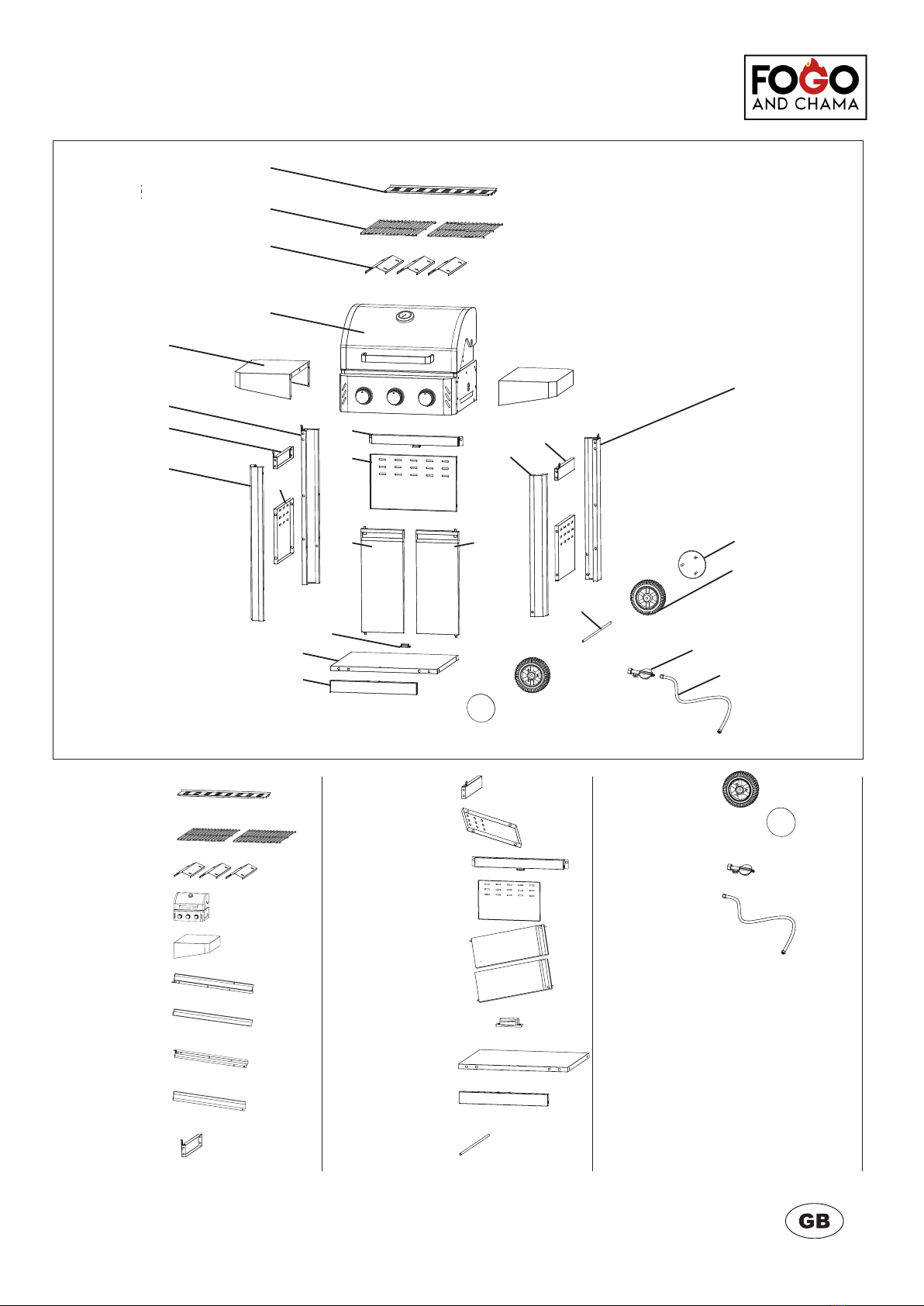
• Check all parts and make sure that no part is missing. Please contact our customer services
if anything is missing.
• A suitable screwdriver and spanner are required for assembly. Make sure to only use tools
that are in good working order and suitable for the job.
Choose a suitable place to set up the appliance. It must be positioned rmly on a at and
suciently sized surface. Make sure that you have the correct inlet and outlet regulators that
match both the cylinder valve and the appliance.
When used outdoors, please ensure that the regulator is protected against weather
inuences. A spanner is required for connecting the gas cylinder.
When connecting the exible tube, please make sure it is not twisted.
Questo manuale è adatto per i seguenti modelli
1
Indice
Altri manuali Fogo & Chama Griglia


