FONESTAR PDA-1408 Manuale utente

INSTRUCTION MANUAL/MANUAL DE INSTRUCCIONES/
MODE D’EMPLOI/MANUAL DE INSTRUÇOES
PDA-1408
LOUDSPEAKER PROCESSOR
PROCESADOR DE ALTAVOCES
PROCESSEUR DE HAUTS-PARLEURS
PROCESSADOR DE ALTIFALANTES
PDA-1408_MANUAL_(EN_ES_FR_PT)_20191119.qxp_Maquetación 1 19/11/19 10:13 Página 1

EN
- 2 -
DESCRIPTION
4-input, 8-output speaker processor designed to process and adapt the audio signal to the characteristics
of the sound system loudspeakers. It processes the input signal and provides an independent signal at each
output.
It features equalization, frequency divider, gain control, limiter, delay and mute functions.
CONTROLS AND FUNCTIONS
FRONT PANEL
1.- Screen showing device information:
a.- Name of the device.
b.- Preset selected.
c.- Software version.
d.- Status of connection between the PC and the device. If the
connection is correct, both icons blink alternately.
e.- DSP indicator. In the event of a problem it will read "DSP!
f.- Device ID number. Obtained automatically.
2.- Navigation buttons.
- UP (PRESET): long press shows the list of presets. Use the UP and DOWN buttons to scroll through
the list and select a preset by pressing and holding the ENTER button to load it. To exit the list,
press and hold UP.
- DOWN (ENTER): pressing and holding the ENTER button displays system information (system and
firmware versions).
To restore the factory settings and clear all saved presets press and hold both UP and DOWN buttons
simultaneously for 8 seconds.
3.- SIGNAL: Indicator light which indicates the presence of a signal on the corresponding input or output
channel.
4.- CLIP: indicator light that indicates signal saturation in the corresponding input or output channel. If it
lights up softly or intermittently, the output volume should be reduced. If the indicator light remains on
continuously, it means that the input signal is extremely high. In this case, reduce the volume of the
input signal.
5.- FAULT: Indicator light indicating a malfunction of the DSP.
6.- COMM: indicator light that provides information on the communication between the PC and the device.
It flashes when data is being transmitted between them. In the case of communication problems it will
remain off.
7.- POWER: Speaker processor power indicator light.
8.- MUTE INPUT: buttons that mute inputs 1-4.
9.- MUTE OUTPUT: buttons that mute outputs 1-8.
PDA-1408_MANUAL_(EN_ES_FR_PT)_20191119.qxp_Maquetación 1 19/11/19 10:13 Página 2

REAR PANEL
1.- Power button.
2.- Power supply 100-240 V AC.
3.- RC-NET IN/LINK: input/output to interconnect several PDA-1408 loudspeaker processors. RJ-45
connector.
4.- Ethernet port. RJ-45 connector.
5.- OUTPUT (1-8): balanced analog audio outputs. XLR connectors.
6.- INPUT (1-4): balanced analog audio inputs. XLR connectors.
7.- FUSE: AC power circuit protection fuse.
8.- RS-232: port for control through serial port. RJ-45 connector.
- 3 -
EN
PDA-1408_MANUAL_(EN_ES_FR_PT)_20191119.qxp_Maquetación 1 19/11/19 10:13 Página 3

CONNECTION
CONNECTING BALANCED AUDIO INPUTS
Each PDA-1408 loudspeaker processor has 4 independent inputs with balanced line-level input for
connecting analog audio sources/microphones. Achieve the best volume for each source by controlling the
input volume via PC software.
CONNECTING BALANCED AUDIO OUTPUTS
Each PDA-1408 loudspeaker processor features 8 independent outputs with balanced line-level output to
enable connection of one power amplifier or amplifier per zone. Connect the output of each zone to a line-
level input of the corresponding power amplifier or amplifier. Control the output volume with PC software and
then adjust the level of the power amplifier or amplifier to get adequate volume in the zone speakers.
GENERAL CONNECTION RECOMMENDATIONS
Turn off and disconnect the speaker processor and all audio system components from power before
attempting to establish any connections. Set volume controls to minimum.
Use suitable and not excessively long cables to make the connections: shielded cables, preferably of a low
capacity. Connect audio sources to inputs. A bad connection can result in noise and interference. Connect
a power amplifier or amplifier to the OUTPUT of each zone you are going to use. You can use 100 V or 4-8
Ω low impedance line amplifiers depending on the type of loudspeakers you are connecting.
Once the connections have been made, connect the devices to the power outlet and turn them on. After
use, remember to turn the power off and unplug the device.
CONNECTION EXAMPLE
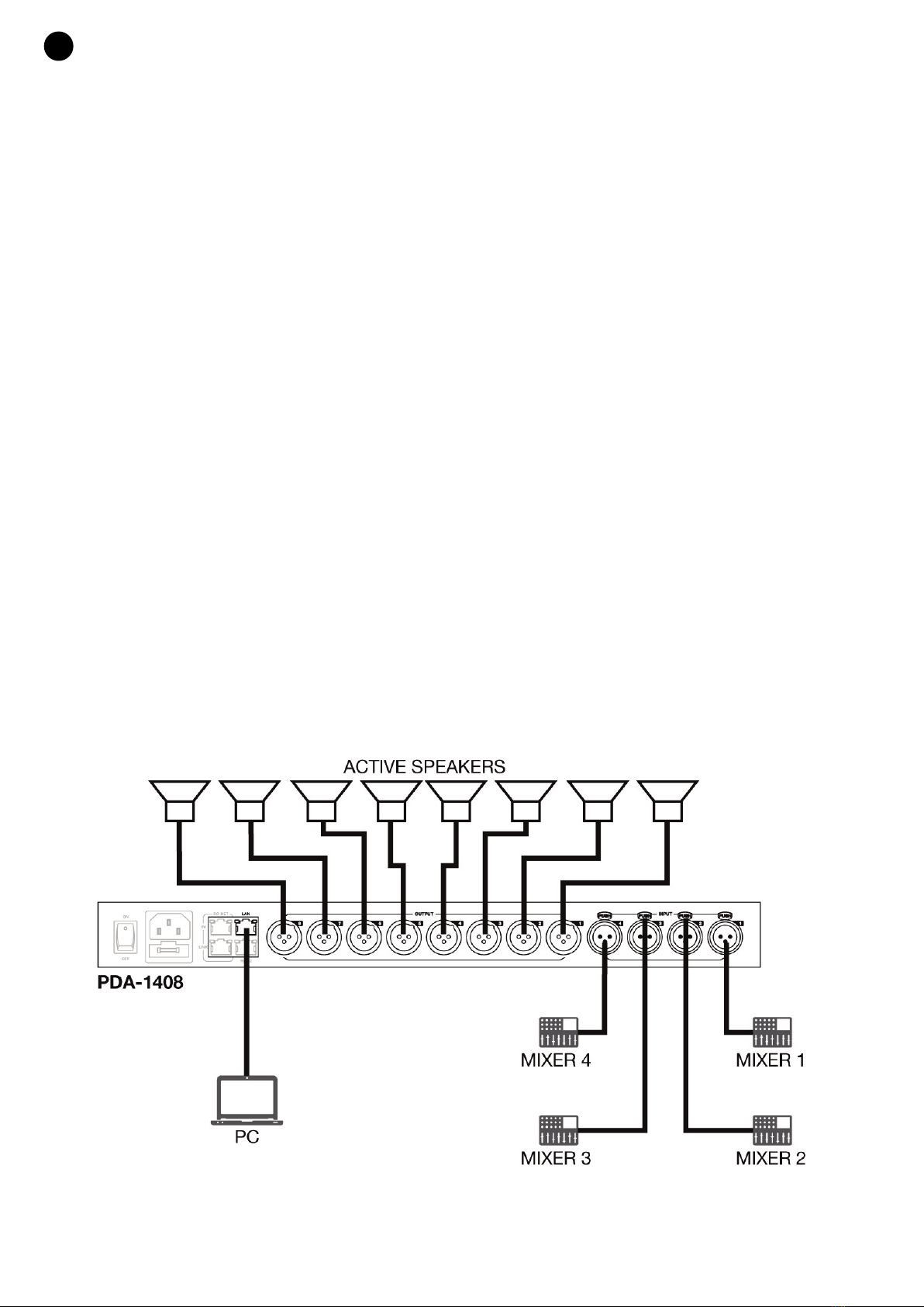
Each PDA-1408 loudspeaker processor allows a maximum of 4 inputs and 8 outputs to be connected. The Daisy
Chain and Star Network connections allow parameters to be controlled and adjusted but do not allow signals to
be shared between processors. Speaker processors are configured using PC software.
CONFIGURATION 1
- 4 -
EN
PDA-1408_MANUAL_(EN_ES_FR_PT)_20191119.qxp_Maquetación 1 19/11/19 10:13 Página 4

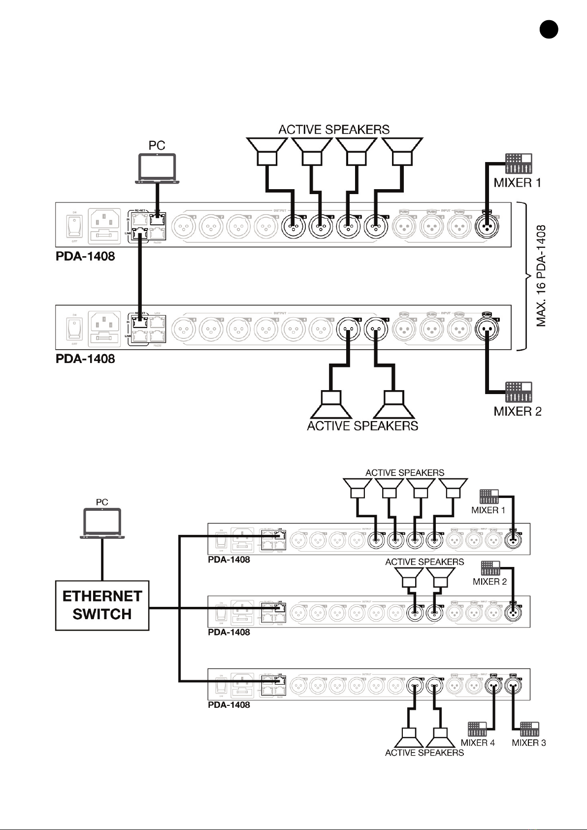
CONFIGURATION 2 (DAISY CHAIN)
The Daisy Chain configuration allows up to 16 PDA-1408 loudspeaker processors to be connected via the RC-
NET port. Connect the LINK output to the IN input of the next processor and so on with the other speaker
processors.
CONFIGURATION 3 (STAR NETWORK)
- 5 -
EN
PDA-1408_MANUAL_(EN_ES_FR_PT)_20191119.qxp_Maquetación 1 19/11/19 10:13 Página 5

- 6 -
CONFIGURATION AND CONTROL SOFTWARE
The PDA-1408 loudspeaker processor is configured using PC software. To download the software, go to
fonestar.com and search for the product PDA-1408. Once there, open the "Software" tab to download the
file to your computer and install the software. This software is compatible with Windows 7 or higher. The
software has two connection modes for speaker processor configuration.
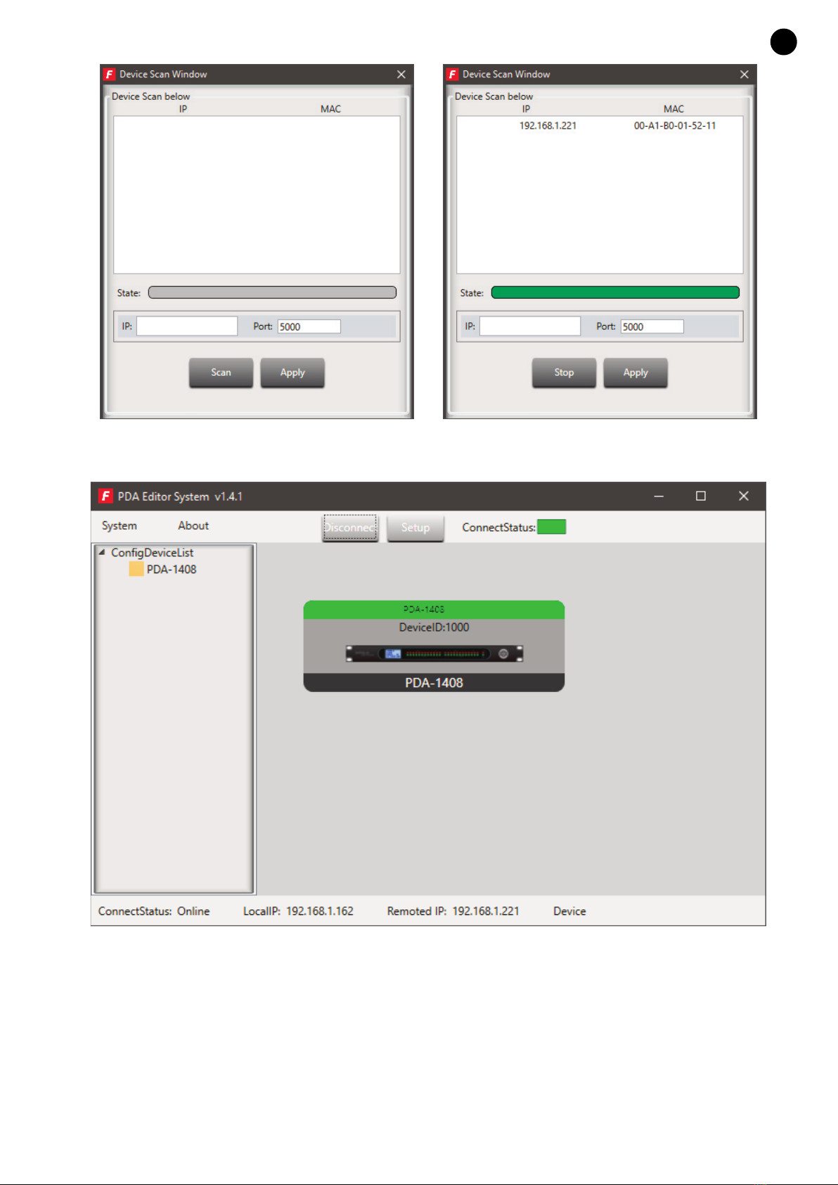
1.- Daisy chain network mode: Used to configure the PDA-1408 loudspeaker processor. In this editing
mode, the PC and PDA-1408 loudspeaker processor must be connected directly by an RJ-45 cable.
It is necessary to set the IP address of the processor. To do this, click the SETUP button and then click
SCAN to start the automatic search for the IP and MAC address of the PDA-1408 loudspeaker processor.
EN
PDA-1408_MANUAL_(EN_ES_FR_PT)_20191119.qxp_Maquetación 1 19/11/19 10:13 Página 6

Select the line with the IP and MAC address of the PDA-1408 loudspeaker processor and click APPLY.
Then click CONNECT and the STATUS indicator should turn green. Add the devices located on the
sidebar by dragging them into the gray area.
Double-click the desired device module to enter edit mode.
Note: To access the configuration of each device, it is necessary to set the device ID manually by right-
clicking on the device to be configured and selecting "Change Device ID".
2.- Star network mode: allows for the configuration and individual control of several PDA-1408 loudspeaker
processors connected to the same router. In this editing mode, the PC and the PDA-1408 loudspeaker
processor must be connected to the RJ-45 cable router.
In this editing mode, the system automatically detects the PDA-1408 speaker processor connected to the
network for configuration and control.
- 7 -
EN
PDA-1408_MANUAL_(EN_ES_FR_PT)_20191119.qxp_Maquetación 1 19/11/19 10:13 Página 7

EDIT MODE
PDA-1408
The edit mode of the PDA-1408 loudspeaker processor allows real-time editing of input/output signal
processing parameters, source zoning, input attenuation per signal level, feedback cancellation, auto-mixing,
saving and loading presets, activating/deactivating relays, renaming the device, and restoring factory settings.
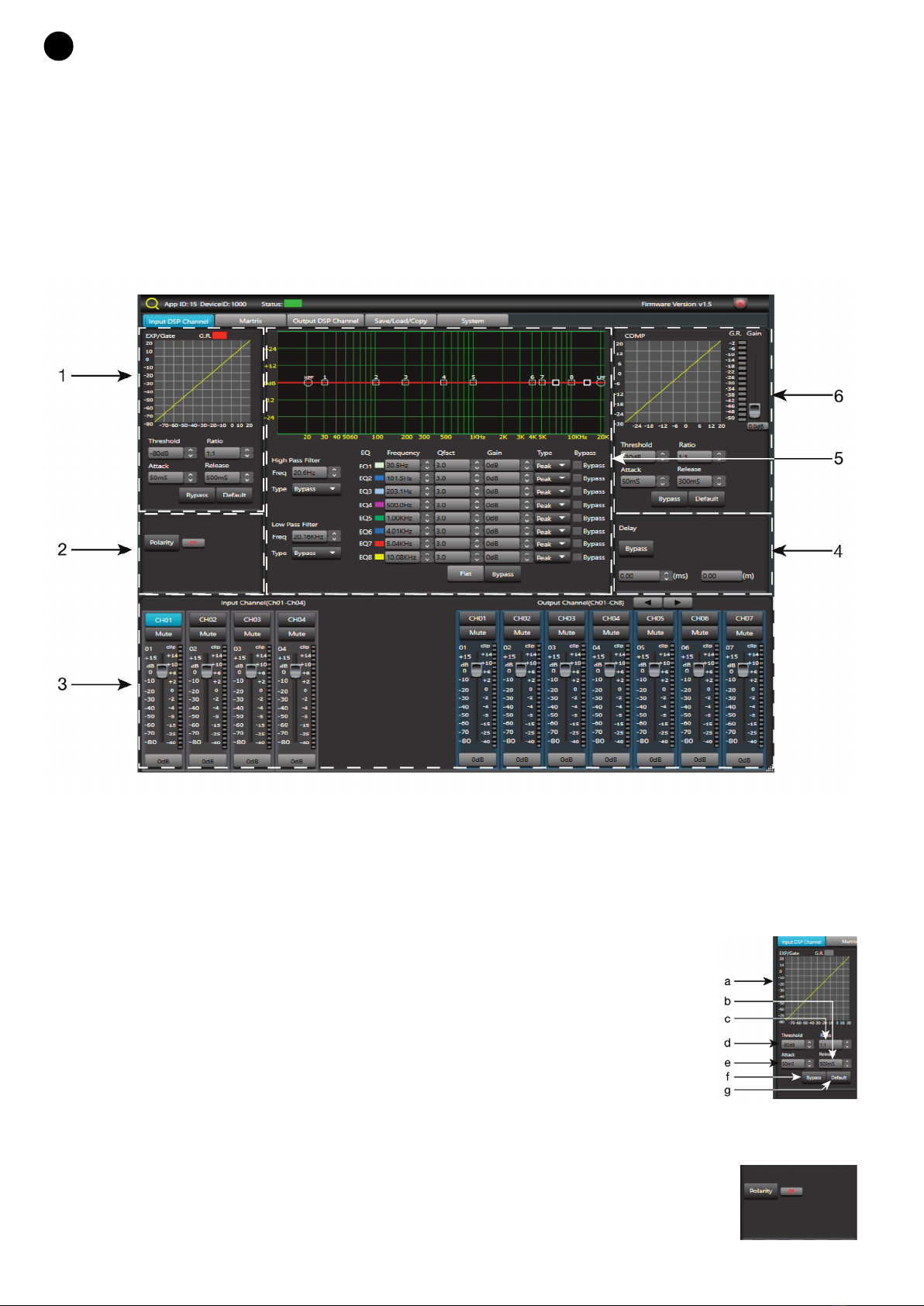
The Input DSP Channel tab is displayed by default.
INPUT DSP CHANNEL
1.- EXP/GATE MODULE:
Adds dynamic range to the signal for each input channel. When the input signal is below the threshold, the
expander amplifies it with the adjusted ratio value. If the signal is above the threshold, the output remains
identical. By setting the ratio value at maximum (Limit), the expander acts as a noise gate.
a.- Visual display of the EXP/GATE module.
b.- Release: expander release time when the signal passes over the threshold value.
c.- Ratio: amplification ratio between the input signal and the amplified signal.
d.- Threshold: threshold value, the signal below this value will be amplified according
to the selected amplification ratio.
e.- Attack: expander reaction time when the input signal is below the threshold value.
f.- Bypass: the input signal is not processed and is diverted to the next processing
module.
g.- Default: restores the default values of the EXP/GATE module.
2.- POLARITY MODULE
Polarity: allows the input signal phase to be inverted by 180º.
- 8 -
EN
PDA-1408_MANUAL_(EN_ES_FR_PT)_20191119.qxp_Maquetación 1 19/11/19 10:13 Página 8

3.- INPUT/OUTPUT CHANNELS
a.- Input/output channel selector (CH1 - CH8).
b.- Mute: mutes the corresponding input/output channel.
c.- Digital signal level fader (-80 to +15 dB).
d.- LED signal level indicator of the input/output channel.
e.- Shows the value of the gain applied to the input/output channel.
4.- DELAY MODULE
a.- Bypass: the input signal is not processed and is diverted to the next
processing module.
b.- Delay: delay applied to the signal of the corresponding input/output channel,
in ms.
5.- EQUALIZATION MODULE
High-pass and low-pass filters to eliminate frequencies above or below the set cutoff frequency.
a.- Freq.: cutoff frequency.
b.- Type: type of filter applied: Bessel, Linkwitz or Butterworth.
8-band parametric equalization. Allows the input signal
spectrum to be modified graphically or by entering the desired
values manually.
c.- Frequency: central frequency.
d.- Qfact: filter quality factor. The higher the value, the smaller the
range of frequencies it affects.
e.- Flat: all equalization parameters are restored to their original value.
f.- Bypass: the input signal is not processed and is diverted to the next processing module.
g.- Gain: elevation or attenuation of the gain in the established central frequency.
h.- Type: type of filter, peak, low pass or high pass.
i.- Bypass 1~8: allows you to temporarily cancel the processing of filters 1 to 8 without the use of the
general bypass.
6.- COMPRESSION MODULE
Limits the signal dynamics for each input channel. When the signal exceeds the threshold, it is compressed
at a ratio greater than 1. Below the threshold, the compressor does not modify the signal. By setting the
ratio to its maximum value (Limit), the compressor acts as a limiter.
a.- Compressor module graphic display.
b.- Threshold: threshold value, the signal above this value, will be compressed
according to the selected compression ratio.
c.- Attack: reaction time of the compressor when the input signal is above the
threshold value.
d.- Ratio: compression ratio between the input signal and the compressed
signal.
e.- Release: compressor release time when the signal passes over the threshold
value.
f.- Default: sets the Compressor module default values.
g.- Bypass: the input signal is not processed and is diverted to the next processing module.
- 9 -
EN
PDA-1408_MANUAL_(EN_ES_FR_PT)_20191119.qxp_Maquetación 1 19/11/19 10:13 Página 9

MATRIX
With the MATRIX function, you assign the inputs to the outputs. Clicking on the grey rectangles turns them
green, indicating the correct assignment of the input channel to the desired output.
IN/OUT 1~4: corresponds to the analog audio inputs/outputs available on the rear panel.
IN/OUT NET 1~8: corresponds to the broadcast inputs/outputs.
OUTPUT DSP CHANNEL
Same menu as Input DSP Channel but without the expander module.
SAVE/LOAD
From the SAVE/LOAD tab you can save/load settings as presets. This data can be stored in the internal
memory of the processor as well as in the PC. The PDA-1408 loudspeaker processor memory holds a total
of 24 presets.
- 10 -
EN
PDA-1408_MANUAL_(EN_ES_FR_PT)_20191119.qxp_Maquetación 1 19/11/19 10:13 Página 10
Indice
Lingue:
Altri manuali FONESTAR Hardware per computer
Manuali Hardware per computer popolari di altre marche

EMC2
EMC2 VNX Series Manuale del proprietario

Panasonic
Panasonic DV0PM20105 Manuale utente

Mitsubishi Electric
Mitsubishi Electric Q81BD-J61BT11 Manuale utente

Gigabyte
Gigabyte B660M DS3H AX DDR4 Manuale utente

Raidon
Raidon iT2300 Manuale utente

National Instruments
National Instruments PXI-8186 Manuale utente