FOR-A GW9014 Manuale utente

GW9014
TeleHealth Gateway
311-9014000-002
Version 1.0 2010/08

2
TABLE OF CONTENTS
INTRODUCTION TO THE SYSTEM 03
Contents of the System 04
Appearance and Key Functions of the Gateway 05
QUICK INSTALLATION STEPS 07
GW9014A 07
GW9014B 09
LED INDICATION AND TRANSMISSION 11
NOTES ABOUT INSTALLATION LOCATION 12
PROBLEM SOLVING GUIDE 13
SPECIFICATIONS 15
SYMBOL INFORMATION 16

3
The FORA GW9014 Gateway works as data receiver and transmitter
which helps users or their healthcare providers to manage the data eas-
ily and remotely. By using this product, healthcare providers can moni-
tor
and analyze your test results remotely and effectively through the
connection to the server. Data results can be viewed in various formats
(HTTP, XML, PPP, SOAP, TCP/IP-, etc.)
The FORA GW9014 Gateway features:
● Simply plug in and test results will automatically upload onto the
server.
● Users and healthcare providers can view the data remotely.
● Data results can be viewed in various formats.
● This device is intended to transmit selected medical information (i.e.
blood glucose, blood pressure, body weight, body temperature, body
fat, and body hydration) measured by compatible devices via RS232
or wireless connections over the internet or residential telephone line.
This system also provides easy connectivity for other compatible de-
vices.
Thank you for purchasing the FORA GW9014 TeleHealth Gateway.
Please read this instruction manual thoroughly before using this device
to ensure safe and accurate use.
INTRODUCTION TO THE SYSTEM
4
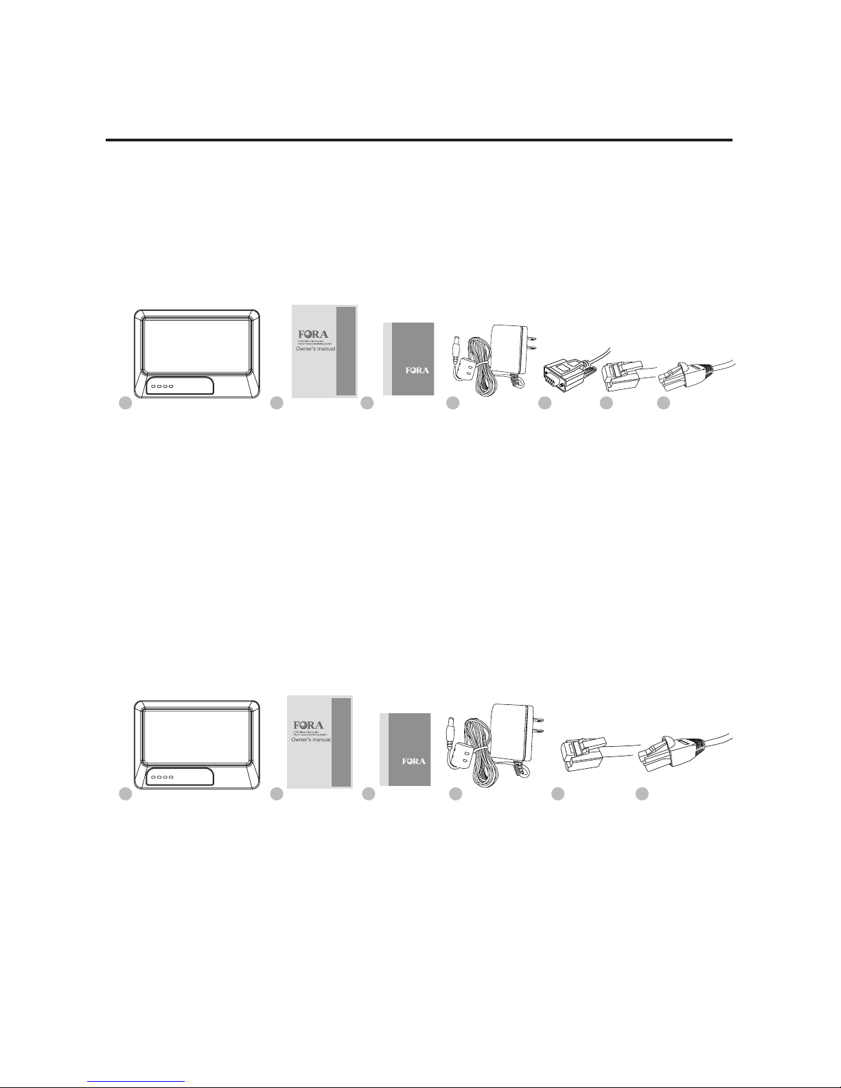
Contents of the System
Before using FORA GW9014 Gateway, please make sure that you have
all the contents listed.
For GW9014A, your system includes:
For GW9014B, your system includes:
3
3
2
2
1
1
4
4
6 75
5 6
FORA GW9014A Gateway
Owner’s Manual
Quick Start User Guide
1 AC Power Adapter
1 RS232 Interface Cable
1 Telephone Line
1 Ethernet Cable
FORA GW9014B Gateway
Owner’s Manual
Quick Start User Guide
1 AC Power Adapter
1 Telephone Line
1 Ethernet Cable
Quick Start User Guide
Quick Start User Guide
5
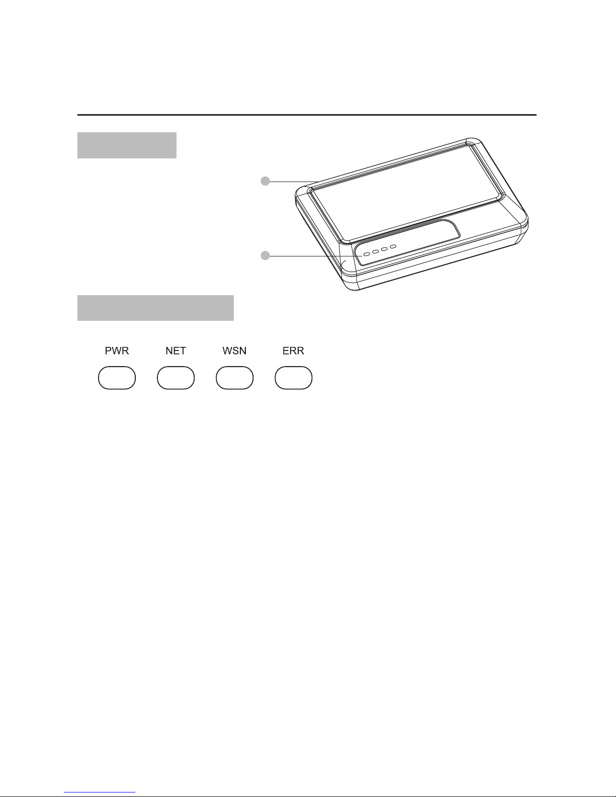
Appearance and Key Functions of the Gateway
Front View
About LED Indicators
2
1
Port Area
Led Indicators Panel
PWR: The status of power supply. Green light will turn solid green if the
power supply is stable. The gateway now is ready for transmis-
sion.
NET: Data transmission status of server. Steady green light indicates
steady connection. Blinking green light indicates that data is
transferring between the server and the gateway. The green
light will not be lit if disconnected.
WSN: Data transmission status indicator of monitoring devices. Steady
green light indicates data transmission between the gateway
and the monitoring device.
ERR: Error message of the gateway. The red light will be lit when error
occurs. Please re-start the gateway or contact customer service
for assistance.
(For more detail information about LED indicators, please refer to page11 “LED
Indication and Transmission”)

6
Bottom View
Back View (GW9014A)
Back View (GW9014B)
Meter Label
For conguration use (Please do NOT open if you are general users)
Power
AC Power Adapter Port
Telephone Line Port
Power
AC Power Adapter Port
Telephone Line Port
Network Cable Port
RS232 Port
Network Cable Port
RS232 Port
(for conguration use only)
21
234 15
234 15
7
QUICK INSTALLATION STEPS
Data Transmission through Ethernet
(FORA GW9014A TeleHealth Gateway contains a build-in DHCP Client
Service)
1. Prepare your internet router (GW9014A contains build-in DHCP Client
Service), and make sure that it can work properly. For the settings of
internet router, please refer to your service carrier's owner manual.
2. Open FORA GW9014 Gateway kit and take out the contents.
3. Plug power adapter into a power outlet and power adapter port on the
gateway.
4. Connect RS232 interface cable with any RS232 available device to
RS232 port on the gateway.
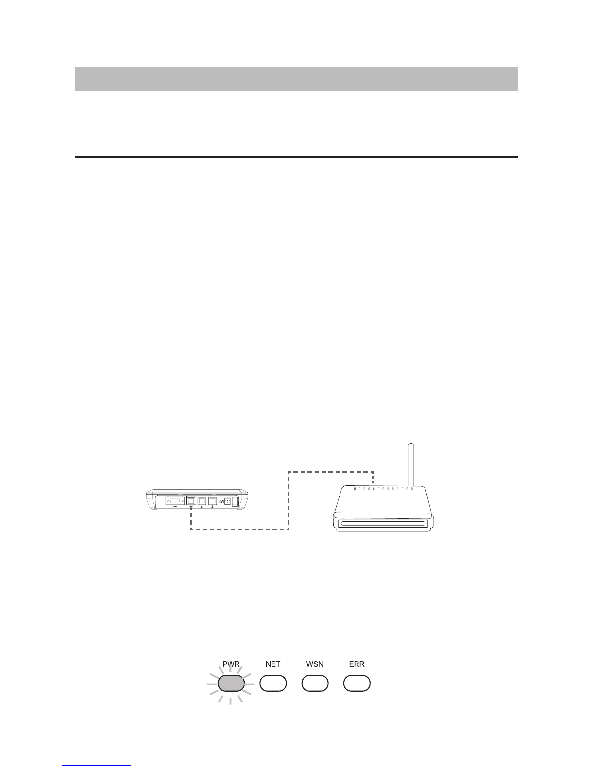
5. Securely insert ethernet cable to internet router and network cable
port on the gateway as illustration below.
Internet Broadband Router
► GW9014A
6. Turn on gateway power. (“O” presents as turn off, “―” presents as
turn on)
7. Congratulations! You have completed all the installation. Please
check if the PWR LED indicators are lit as the illustration below.
8
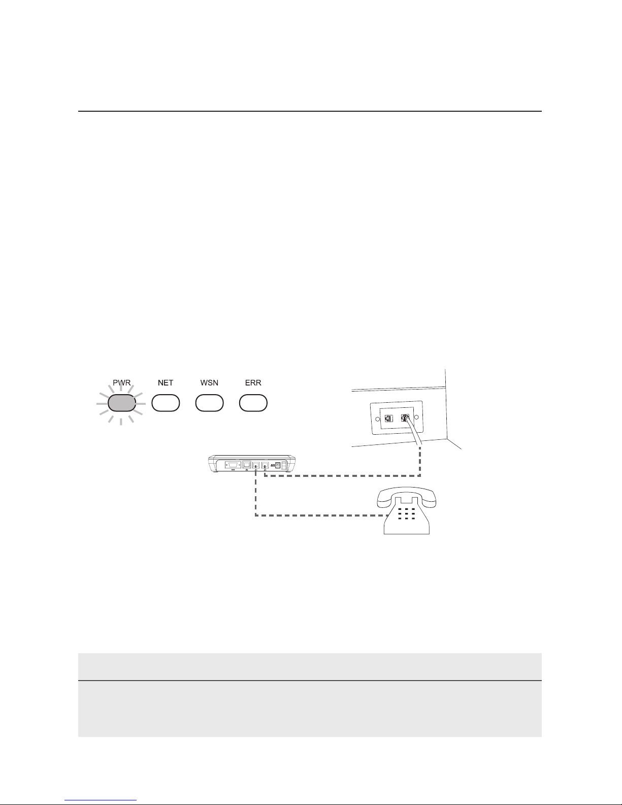
Data Transmission through Telephone Line
(FORA GW9014A Gateway contains built-in ISP dial-up service.)
1. Open FORA GW9014 Gateway kit and take out the contents.
2. Plug power adapter into a power outlet and power adapter port on the
gateway.
3. Connect RS232 interface cable to RS232 port on the gateway.
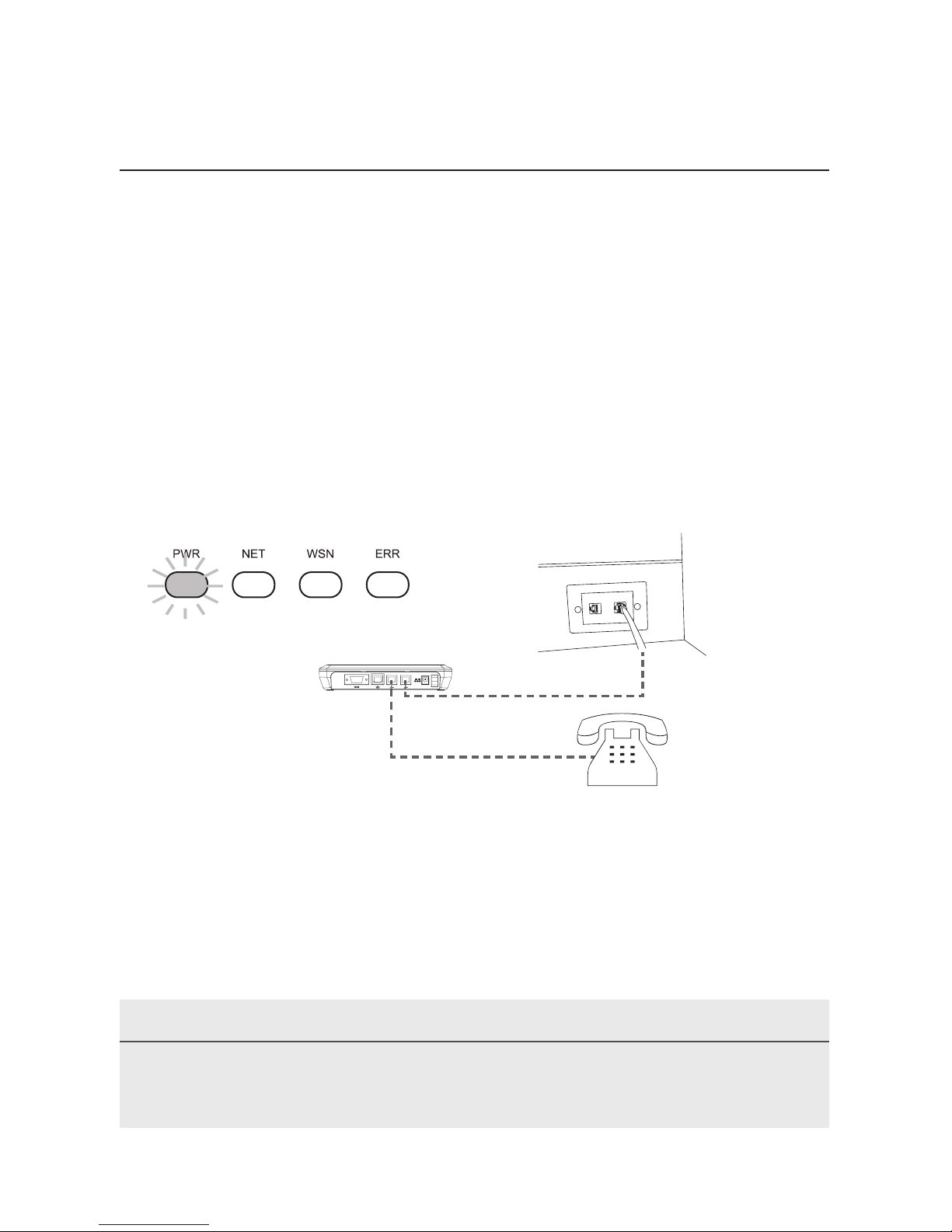
4. Securely insert telephone line into one of the telephone line port on
the gateway. If you want to use telephone, please insert its telephone
line to another telephone line port on the gateway.
5. Turn on gateway power. (“O” presents as turn off, “―” presents as
turn on)
6. Congratulations! You have completed all the installation. Please
check if the PWR LED indicator is lit as the illustration below.
(Tel-Line)
(Phone)
PLEASE NOTE
You can choose either Ethernet or telephone line to transmit data. Do not
use both of them at the same time.

9
PLEASE NOTE
You will need to connect any Bluetooth available device with the FORA
GW9014 (GW9014B only) Gateway .
Data Transmission through Ethernet
(FORA GW9014B TeleHealth Gateway contains a build-in DHCP Client
Service)
1. Prepare your internet router (GW9014B contains build-in DHCP Client
Service), and make sure that it can work properly. For the settings of
internet router, please refer to your service carrier's owner manual.
2. Open FORA GW9014 Gateway kit and take out the contents.
3. Plug power adapter into a power outlet and power adapter port on the
gateway.
4. Securely insert Ethernet cable to internet router and network cable
port on the gateway as illustration below.
Internet Broadband Router
► GW9014B
5. Turn on Gateway power. (“O” presents as turn off, “―” presents as
turn on)
6. Congratulations! You have completed the installation. Please check if
the PWR LED indicators are lit as the illustration below.
10
Data Transmission through Telephone Line
(FORA GW9014B Gateway contains built-in ISP dial-up service.)
1. Open FORA GW9014 Gateway kit and take out the contents.
2. Plug power adapter into a power outlet and power adapter port on the
gateway.
3. Securely insert telephone line into one of the telephone line port on
the gateway. If you want to use telephone, please insert its telephone
line to another telephone line port on the gateway.
4. Turn on gateway power. (“O” presents as turn off, “―” presents as
turn on)
5. Congratulations! You have completed the installation. Please check if
the PWR LED indicator is lit as the illustration below.
(Tel-Line)
(Phone)
PLEASE NOTE
You can choose either Ethernet or telephone line to transmit data. Do not
use both of them at the same time.
Indice
Altri manuali FOR-A Portale


Manuali Portale popolari di altre marche

LST
LST M500RFE-AS Manuale utente

Kinnex
Kinnex Media Gateway Manuale utente

2N Telekomunikace
2N Telekomunikace 2N StarGate Manuale utente

Mitsubishi Heavy Industries
Mitsubishi Heavy Industries Superlink SC-WBGW256 Manuale utente

ZyXEL Communications
ZyXEL Communications ZYWALL2 ET 2WE Manuale utente

Telsey
Telsey CPVA 500 - SIP Manuale utente


