Page 7
- 3.3 Trouble shooting ! You will need an analogue or digital voltmeter for some of these tests.
1. When did the fault begin?
Where a system has been working for a while, and then
a fault develops, it is likely that the fault is in the wiring.
Where the intercom has never worked, it may be miss-
wired, or even a faulty component.
2. Elimination
For systems with two screens or two camera panels, it
is possible to swap the two similar parts. For example,
by swapping two screens over, if the problem followed
the screen, then the screen could be faulty. If however
the problem stayed at the same position, then the
wiring or supply might be at fault. If there is another
system on site, substituting components one by one
may find the faulty part.
Often it is the wiring that has failed. Try taking the
camera panel to within a few feet of the screen, then
connect the screen to the camera panel using a short
new cable. Be sure to disconnect the original cable first.
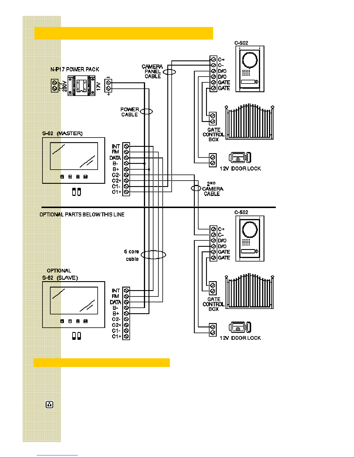
3. Cable checks
The wiring or two wire systems is very simple to test.
You will need a digital meter Switch off system. Take
the cover off the camera panel and take the screen off
the wall. Insert a shorting link between terminals +
and -. Measure the resistance at the other end of the
cable. The value should be less than 5 ohms.
The same check can be done on the power supply
cable, but the resistance must be less than 2 ohms.
Be sure to remove any shorts before restoring power.
Switching on
When the power is first turned on, there is a short delay
(from 1 to 3 seconds). Then the buttons on the screen
are lit blue at the same time as the nameplate on the
camera panel lights up blue.
If this doesn’t happen, the voltage checks will be likely
to show the problem.
If the screen begins ringing immediately, then there is a
cable problem. Return to ‘ able hecks’.
5 Voltage checks
The most important consideration is that the polarity is
correct. + and B+ are positive. - and B- are negative.
Turn the power on and measure the voltage across the
power pack output. With the red lead on B+ and the
black on B-, the voltmeter should be about +17V.
Repeat the voltage checks on the camera cable. With
the red lead on + and the black on -, the voltmeter
should be about +3.5V.
6 Video function
Touch the recall button recall. The screen should
show the outside view.
If there is no picture but a buzz, check the power to the
screen on terminals B+ and B-. (It should still be 17V).
If there is no picture, or the picture is poor, flickering,
unstable or black & white, the cable to the camera
panel may be the problem. Try connecting the camera
panel to the screen on another short length of cable.
7 Audio function
Generally, if the video is functioning, the audio will also.
In some modes, the audio only works in one direction.
Refer to section 1.3.
Sound quality can be affected by bad connections or
poor cable to the camera panel. A high resistance will
reduce the voltage on + and -. (it should be 13.5V).
Buzzing, humming or other noises may be picked up
from equipment that the cable passes. See section 2.3.
Try turning off appliances, radios or TV in the area.
8 Door release function
The power for the door release is stored in the camera
panel. It is 10mJ which is only suitable for small strikes.
To test it, open the door and rest light finger pressure
on the strike. If it jolts, the power is getting to the strike.
Your strike may be polarity sensitive. Try reversing the
D/O terminals on the camera panel and test again.
The strike may be faulty, or not 12V rated. Disconnect it
from the panel and connect it to a 12V test battery.
9 Gate release function
The gate release output on ‘GATE’ terminals is a volt
free contact (like a push button). If these terminals are
connected to a gate panel, there will be a voltage on it.
Momentarily short the two terminals together. heck
the gate opens. You should also hear a small click from
the camera panel. If the gate still does not open, the
fault is not with the intercom.
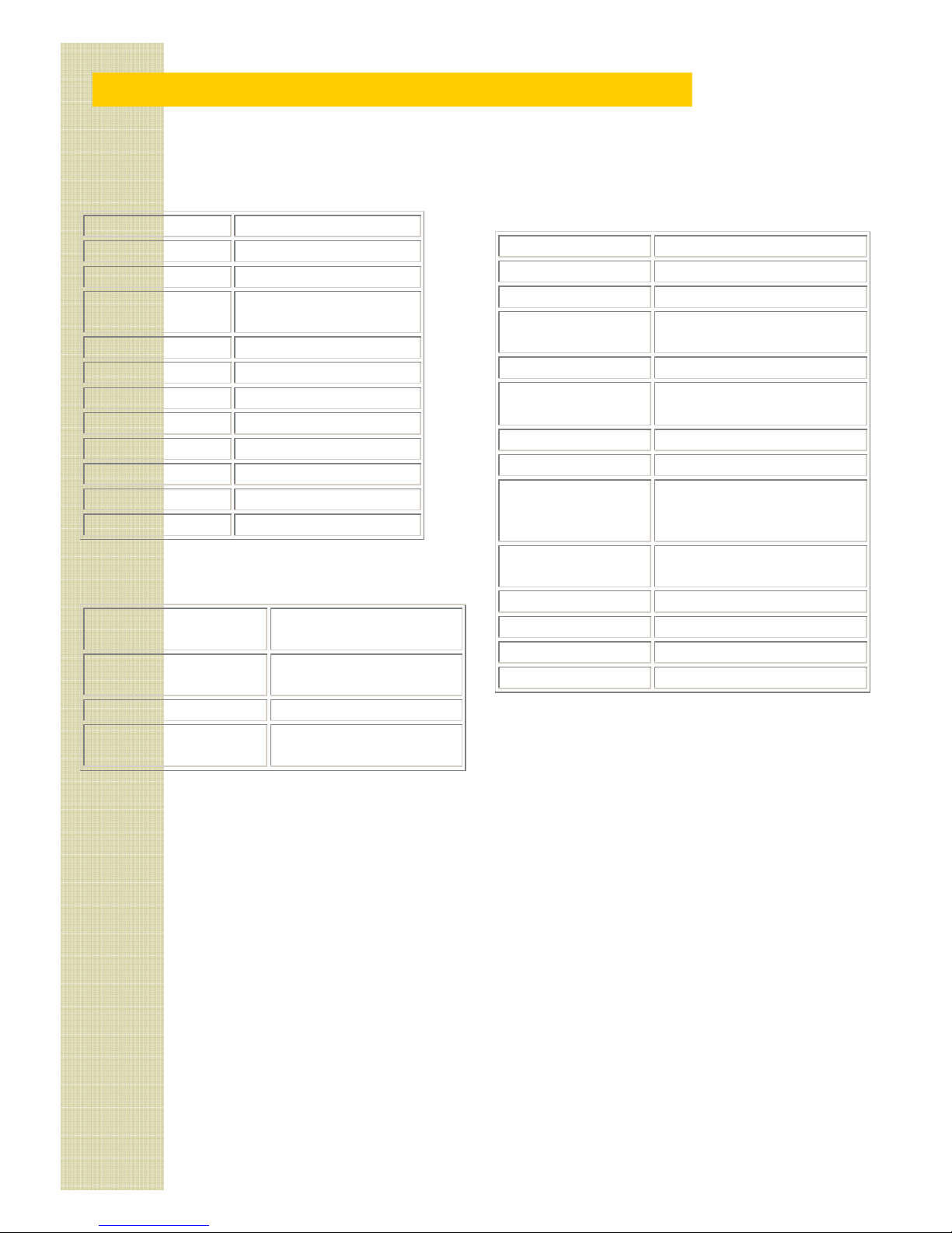
Summary of voltages
Measuring camera voltage on terminals + and -.
Dormant state 3.5V 50mA
While calling 13.5V 550mA
During call 13.5V 550mA
Power pack voltage on B+ and B- should be 17V at all
times. D/O terminals give a 12V pulse for <1 sec.
Summary of faults
No screen lights Power supply fault
No camera light able fault to the camera panel
Loss of colour Bad or incorrect cable
Audio, no video Poor cable to camera panel