FOTILE GLG30301 Manuale utente

INSTALLATION
MANUAL
Gas Cooktop
Read all instructions before
using this appliance
GLG30301 GLG30401-Y GLG30401
1102002508070
Tous les efforts ont été faits pour sʼassurer que les informations fournies dans ce manuel
sont correctes au moment de lʼimpression. Cependant, en raison de lʼamélioration continue
des produits, FOTILE se réserve le droit de modifier les produits et les données techniques
sans préavis.
Société à responsabilité des ustensiles de cuisine de Ningbo FOTILE
N°218, Rue N°2 de Binhai, Nouvelle zone de Hangzhouwan, Ville de Cixi, Province du Zhejiang, Chine
WWW.FOTI LEGLOBAL.COM

-2--1-
Contents
Important Safety Information
Packing List And Tools
Before You Begin
Product Dimensions
Clearance Dimensions
Installation Requirements
Installation Instructions
Installing The Cooktop
Connecting The Cooktop To Gas Supply
Electrical Connections
Burner Components And Grate Installation
Check The Ignition And Flame Quality
LP Conversion Instructions
2
6
7
7
9
8
11
12
13
16
13
18
11
Read all instructions before using this appliance
Save this manual. Please do not discard.
We have provided many important safety messages in this manual and on your appliance.
Always read and obey all safety messages.
All safety messages will tell you what the potential hazard is, tell you how to reduce the chance
of injury, and tell you what can happen if the instructions are not followed.
You can be killed or seriously injured if you do not immediately follow
instructions.
You can be killed or seriously injured if you do not follow instructions.
This is the safety alerts symbol.
This symbol alerts you to potential hazards that can kill or hurt you and others.
All safety messages will follow the safety alerts symbol and either the word
“DANGER” or “WARNING.”
These words mean:
Your safety and the safety of others are very important
DANGER
WARNING
WARNING
0M[OLPUMVYTH[PVUPU[OPZTHU\HSPZUV[MVSSV^LKL_HJ[S`HMPYLVYL_WSVZPVUTH`YLZ\S[
JH\ZPUNWYVWLY[`KHTHNLWLYZVUHSPUQ\Y`VYKLH[O
¶+VUV[Z[VYLVY\ZLNHZVSPULVYV[OLYMSHTTHISL]HWVYZHUKSPX\PKZPU[OL]PJPUP[`VM[OPZVY
HU`V[OLYHWWSPHUJL
¶>/(;;6+60-@6<:4,33.(:!
+VUV[[Y`[VSPNO[HU`HWWSPHUJL
+VUV[[V\JOHU`LSLJ[YPJHSZ^P[JO
+VUV[\ZLHU`WOVULPU`V\YI\PSKPUN
0TTLKPH[LS`JHSS`V\YNHZZ\WWSPLYMYVTHULPNOIVYZWOVUL-VSSV^[OLNHZZ\WWSPLYZ
PUZ[Y\J[PVUZ
0M`V\JHUUV[YLHJO`V\YNHZZ\WWSPLYJHSS[OLMPYLKLWHY[TLU[
¶0UZ[HSSH[PVUHUKZLY]PJLT\Z[ILWLYMVYTLKI`HX\HSPMPLKPUZ[HSSLYZLY]PJLHNLUJ`VY[OL
NHZZ\WWSPLY
Important safety information

-4--3-
WARNING
INSTALLATION PRECAUTIONS
WARNING
Gas leaks cannot always be detected by smell.
Gas suppliers recommend that you use a gas detector approved by UL or CSA.
For more information, contact your gas supplier.
WARNING
5L]LYVWLYH[L[OL[VWZ\YMHJLJVVRPUNZLJ[PVUVM[OPZHWWSPHUJL\UH[[LUKLK
-HPS\YL[VMVSSV^[OPZ^HYUPUNZ[H[LTLU[JV\SKYLZ\S[PUMPYLL_WSVZPVUVYI\YUOHaHYK[OH[
JV\SKJH\ZLWYVWLY[`KHTHNLWLYZVUHSPUQ\Y`VYKLH[O
0MHMPYLZOV\SKVJJ\YRLLWH^H`MYVT[OLHWWSPHUJLHUKPTTLKPH[LS`JHSS`V\MPYLKLWHY[
TLU[+656;H[[LTW[[VL_[PUN\PZOHUVPSNYLHZLMPYL^P[O^H[LY
IMPORTANT
Do not install a ventilation system that blows air downward toward this gas cooking appliance. This
type of ventilation system may cause ignition and combustion problems with this gas cooking appli-
ance resulting in personal injury or unintended operation.
STATE OF CALIFORNIA PROPOSITION 65 WARNINGS
WARNING
This product contains one or more chemicals known to the State of California to cause cancer, birth
defects or other reproductive harm.
Gas appliances can cause low-level exposure to some of these substances, including benzene,
carbon monoxide, formaldehyde and soot, caused primarily by incomplete combustion of natural
gas or propane fuels.
Exposure to these substances can be minimized by opening a window or using a ventilation fan or
hood.
STATE OF MASSACHUSETTS
In the State of Massachusetts, the following installation instructions apply:
• Installations and repairs must be performed by a qualified or licensed contractor, plumber, or
gasfitter qualified or licensed by the State of Massachusetts.
• If using a ball valve, it shall be a T-handle type.
• A flexible gas connector, when used, must not exceed 3 feet.
Electrical shock hazard
Failure to do so could result in electrical shock or death.
Cut hazard
Take care-panel edges are sharp.
Failure to use caution could result in injury or cuts .
Ŗ!Important safety precautions
• Particular attention shall be given to the relevant requirements regarding ventilation.
• Please make this information available to the person installing the appliance as it could reduce
your installation costs.
• This appliance is to be installed and connected to gas supply only by an authorised person.
• Installation must comply with your local building and local gas authority codes and electricity
regulations.
• Failure to install the appliance correctly could invalidate any warranty or liability claims.
• This gas appliance is suitable for connection to natural gas and can convert to LPG only. If in
doubt, refer to the local gas network operator or gas supplier to confirm gas type at installation
site.
Ŗ!Before you install the appliance, please make sure that
• The local distribution conditions(nature of gas and pressure) and the adjustment of the appliance
are compatible. For adjustment conditions for this appliance check data plate for relevant gas
information.
• The supply connection point (gas shut-valve) is accessible after installation. The regulator
supplied with Natural gas appliances must be fitted to the appliance inlet.
Ŗ!When you install the appliance
• We do not recommend the use of a down-draught extractor fan with the appliance, as it may
distort the flame pattern, causing uneven heating and reduced cooking performance.
• Where this appliance is installed in marine craft or in caravans, it shall not be used as a space
heater.Only models fitted with the flame failure device can be fitted in marine craft. No combusti-
ble material or products should be placed on this appliance at any time.
• Do not spray aerosols in the vicinity of this appliance while it is in operation.
• If, after following the instructions given, the appliance cannot be adjusted to perform correctly,
please refer to the Service & Warranty book for warranty details and your nearest Authorised
Service Centre,or contact FOTILE Customer Care at:
Important safety information Important safety information
1-888-315-0366 (U.S.) [email protected]
1-844-315-0315 (CA) service@fotileca .com

-6--5-
Our products are only packaged using non-pollutant, environment-friendly, recyclable materials. We
urge you to cooperate by disposing of the packaging properly. Contact your local dealer or the compe-
tent local organizations for the addresses of collection, recycling and disposal facilities.
Never leave all or part of the packaging lying around. Packaging parts, and especially plastic bags, may
represent a suffocation hazard for children.
Your old appliance must also be disposed of properly. Important: deliver the appliance to your local
organization authorized to collect scrapped appliances. Proper disposal allows the intelligent recovery
of valuable materials.
Note: In this document, we take the image of model GLG30401-Y/GLG30401 as an example.
Compared with it, model GLG30301 does not have Simmer Burner and its control knob, and the
Center Grate is slightly different.
• Gas line shut-off valve
• Professional gas pipeline sealing materials that resists action of natural and propane gases
• Flexible metal appliance connector (3/8 NPT).
A 5-foot length is recommended for ease of installation but other lengths are acceptable.
Never use an old connector when installing a new cooktop.
• Flare union adapter for connection to gas supply line (3/4 or 1/2 NPT × 3/8 NPT).
• Flare union adapter for connection to pressure regulator on cooktop (1/2!NPT x 3/8 NPT).
• Liquid leak detector or soapy water.
Never leave packaging residues unattended in the house. Separate waste packaging materi-
als by type and consign them to the nearest separate disposal centre.
Ŗ!Materials You May Need
PACKAGE DISPOSAL INSTRUCTIONS - ENVIRONMENT POLICY
Packing List And ToolsImportant safety information
WHATʼS INCLUDED
Ŗ!Packing list and tools Ŗ!Tools You Will Need
Pencil and ruler
Safety Glasses
Phillips screwdriver
Open-end or
adjustable wrench
Saber Saw
1/8” Drill Bit & Electric
or Hand Drill
3/16” Flat-blade screwdriver
Pipe wrenches(2)
(one for backup)
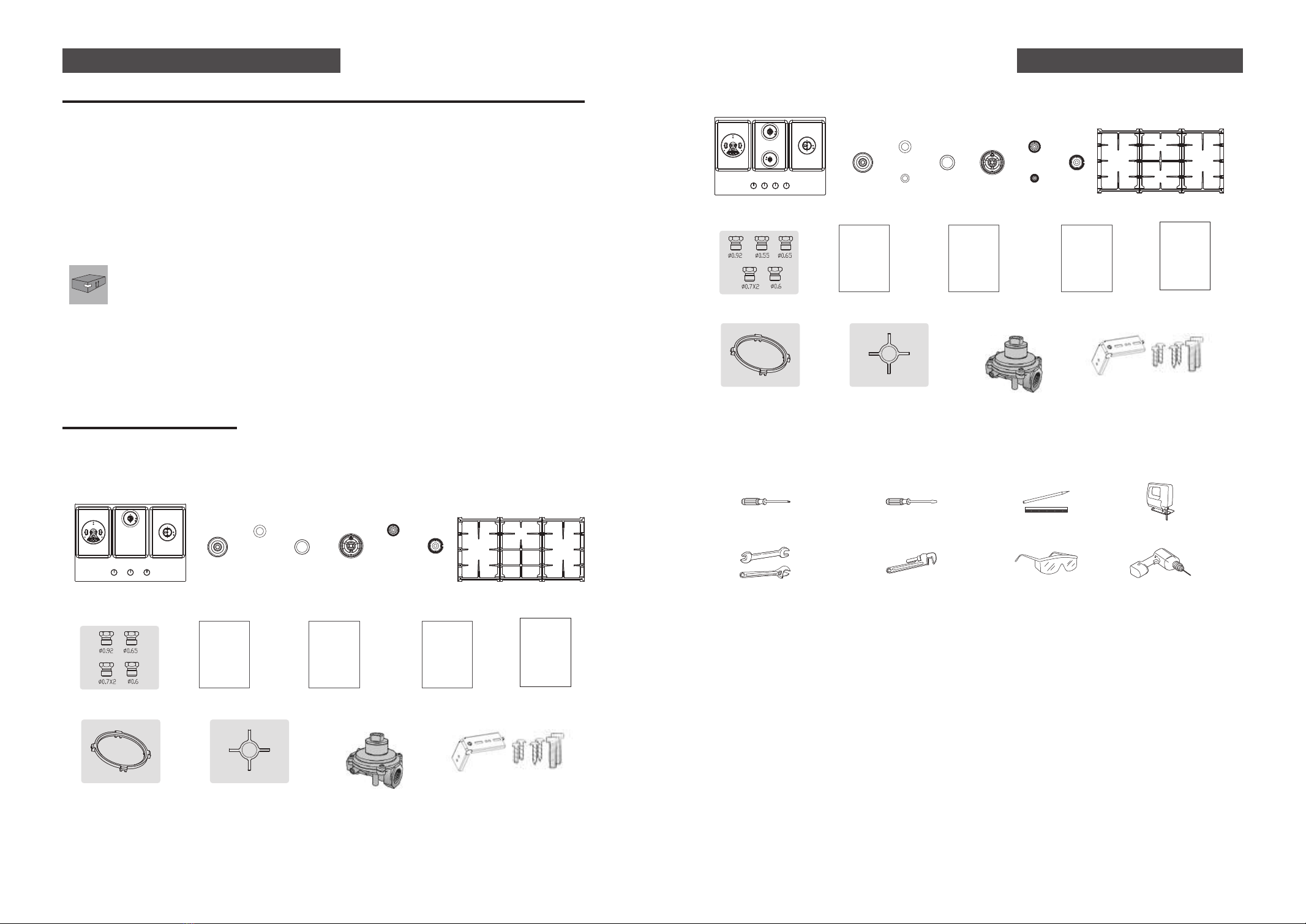
Cooktop (1)
Nozzles for LPG (5) Installation Manual (1)
Pressure regulator (1)
User Manual (1) Warranty Card (1) Cover Sheet (1)
Wok Grate (1) Tea Kettle Grate (1) Panel mounting brackets (2)
Screws (6)
L8X2 L13X2 L70X2
Grates (3)
Burner Caps (4)Burner Heads (3)
GLG30301
Nozzles for LPG (6) Installation Manual (1)
Pressure regulator (1)
User Manual (1) Warranty Card (1) Cover Sheet (1)
Wok Grate (1) Tea Kettle Grate (1) Panel mounting brackets (2)
Screws (6)
L8X2 L13X2 L70X2
Cooktop (1)Burner Caps (5)Burner Heads (4)
GLG30401-Y/GLG30401
Grates (3)

-8--7-
Ŗ!Clearance Dimensions
Above the cooktop
The minimum safety distance given by the hood manufacturer must be maintained between the
cook top and the hood above it. See the installation instructions of the hood for these safety
measurements. If the hood manufacturerʼs instructions are not available or if flammable objects are
installed over the cook top (e.g. cabinets, utensil rail, etc.), a minimum safety distance of 30" (760
mm) must be maintained.
Minimum vertical clearances of 18 inches from top surface unit to side cabinets. Minimum horizontal
distance(s) from sides and back of appliance to adjacent vertical combustible walls extending above
the top panel, 12 inches from the left side, 12 inches from right side, 2 7/8 inches from rear wall.
Minimum clearance to combustible construction centered above cooking surface: vertical 30
inches, horizontal 30 inches. The unit overhead cabinet maximum depth: 13 inches. Minimum
horizontal distance from front edge of counter to front side of appliance, 1/4 inches.
If there are several appliances beneath a hood, and they have different minimum safety distances
always observe the largest distance.
Below the cooktop
All gas cooktop models require 7/16ʼʼ free area below cooktop height to combustible material.
Safety distances
1. Remove packing materials from the cooktop.
2. Make sure you have received all of the supplied parts shown above in the parts list.
3. Check that the cooktop is in good condition without damage during unpacking.
4. Check the dimensions and clearances (shown below), make sure the inside of the cabinet and the
cooktop do not interfere with each other.
Before you begin Before you begin
Product Dimensions (W x D x H) (inch):30 x 21 x 7 3/16
Cut-out Dimensions(W x D) (inch):28 1/2 x 19 5/8
Product Dimensions (W x D x H) (mm):762 x 533 x 182
Cut-out Dimensions(W x D) (mm):724 x 499
Ŗ!Product Dimensions
12 3/4" Min.
[323mm]
12 3/4" Min.
[323mm]
3 9/16" Min.
[91mm]
Rear wall
28 1/2" [724mm]
19 5/8" [499mm]
13" Max.
[330mm]
7 3/16"
[182mm]
6 5/16"
[160mm]
3 1/4"
[82mm]
1 7/16"
[37mm]
19 3/16"
[488mm]
21"
[533mm]
28 1/4"
[718mm]
30"
[762mm]
2 7/8"Min
[73mm]
12"Min
[305mm]
12"Min
[305mm]
1/4"Min
[6mm]
Rear wall
18" Min.
[457mm]
30" Min.
[762mm]
1" Min
[25.4mm]

-10--9-
WARNING
Electrical outlet 12” (30.5 cm) minimum below countertop
All gas models are equipped with a power cord with an equipment-grounding conductor and a
grounding plug.
A 120-Volt, 60-Hz, AC, approved electrical service with 20-amp circuit breaker or time-delay fuse
is required for all U.S. and Canadian models.
The plug must be firmly plugged into a three-prong outlet that is properly installed and grounded
in accordance with local codes or, in the absence of local codes, with the National Electrical Code,
NFPA 70 or the Canadian Electric Code, CSA C22.1-02. In the event of a malfunction or break-
down, grounding will decrease the risk of electrical shock by providing a path for the electric
current.
Provide adequate gas supply
Explosion Hazard
Use a new CSA/ETL International approved gas supply line.
Install a shut-off valve.
Securely tighten all gas connections.
If connected to LP, have a qualified person make sure gas pressure does not exceed 14ʼʼ
(36cm) water column.
Examples of qualified person include:
Licensed heating personnel
Authorized gas company personnel, and
Authorized service personnel.
Failure to do so can result in death, explosion, or fire.
WARNING
The pressure regulator located at the inlet of the cooktop manifold must remain in the supply
line regardless of whether natural or LP gas is being used.
This cooktop is designed to operate at a pressure of 4in (10cm) of water column on natural gas or 10in
(25cm) of water column on LP gas.
Make sure you are supplying your cooktop with the type of gas for which it is designed. Do not attempt
to convert the appliance from the gas specified in this manual to a different gas without consulting the
gas supplier.
This cooktop is convertible for use on natural or propane gas. If you decide to use this cooktop on LP
gas, conversion must be made by a qualified LP installer before attempting to operate the cooktop.
For proper operation, the pressure of natural gas supplied to the regulator must be between 4in and
10in (10cm and 25cm) of water column.
For LP gas, the pressure supplied must be between 10in and 13in (25cm and 33cm) of water column.
When checking for proper operation of the regulator, the inlet pressure must be at least 1in (2.5cm)
greater than the operating (manifold) pressure as given.
WARNING
Electrical Shock Hazard
Plug into a grounded 3 prong outlet.
Do not remove ground prong.
Do not use an adapter.
Do not use an extension cord.
Failure to follow these instructions can result in death, fire, or electrical shock.
Installation requirements Installation requirements
Ŗ!Gas supply requirements Ŗ!Electrical requirement

-12--11-
• FOTILE gas cooktops are manufactured and shipped to be used with natural gas. If you want to
use LPG, please convert before using.
• To prevent gas leaks, please use professional gas pipe sealing materials on all male (external)
pipe threads.
• Attach the gas pressure regulator (included with the cooktop) to the cooktop pipe nipple inlet. For
tight installations, the regulator may be installed upstream from the pipe nipple, anywhere
between the shut-off valve and the cooktop. For best performance, minimize gas pressure loss by
attaching the regulator as close as possible to the cooktop gas inlet.
• When all connections have been made, make sure all cooktop controls are in the off position and
turn on the main gas supply valve.
• Use Soap-suds at all joints and connections to check for leaks in the system.
• Tighten all connections if necessary to prevent gas leakage in the cooktop or supply line.
Ŗ!Step 1: Installing the cooktop
• Locate electrical outlet and gas shut-off valve beneath the cabinet.
• Insert the cooktop centered into the cutout opening. Make sure the front edge of the countertop
is parallel to the cooktop. Make final check that all required clearances are met.
* Be careful that the ignition needle/thermocouple is not damaged by inserting.
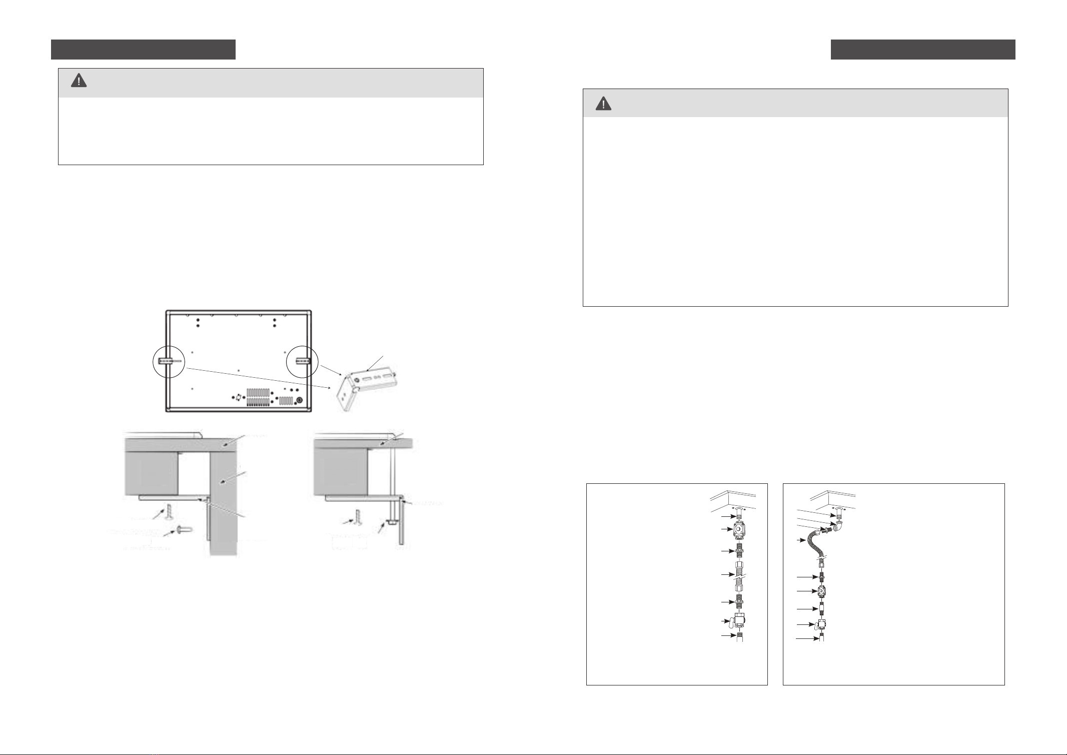
• Choose installation method 1 or method 2 shown below to secure the cooktop to the countertop
using the two provided hold-down brackets as shown.
Please read the following instructions, as well as the Important Safety Instructions section at the
front of this manual, completely and carefully BEFORE installing and/or operating the gas cooktop.
Improper installation, adjustment, service, or maintenance can cause personal injury or property
damage.
WARNING
Shut off the main gas supply valve before disconnecting the old cooktop and leave it off until the new
hookup has been completed. Donʼt forget to relight the burner on other gas appliances when you turn
the gas back on.
Because hard piping restricts movement of the cooktop, the use of a CSA International-certified flexible
metal appliance connector is recommended unless local codes require a hard-piped connection.
Never use an old connector when installing a new cooktop. If the hard-piping method is used, you
must carefully align the pipe; the cooktop cannot be moved after the connection is made.
Tighten all connections if necessary to prevent gas leakage in the cooktop or supply line.
Check for gas leaks: To prevent death, personal injury, explosion, and/or fire hazard, DO NOT use a
flame to check for gas leaks. When using test pressures greater than ½ psig to pressure-test the gas
supply system of the residence, disconnect the cooktop and individual shut-off valve from the gas
supply piping. When using test pressures of ½ psig or less to test the gas supply system, simply
isolate the cooktop from the gas supply system by closing the individual shut-off valve.
Ŗ!Step 2: Connecting the cooktop to gas supply
Installation instructions Installation instructions
88
70M5
13
WARNING
Installation Method 1 Installation Method 2
No appliance/obstructions
below cooktop
A
B
C
D
E
F
G
A. 1/2” NPT male pipe thread
B. Regulator provided with
unit:
• Outlet - 1/2” NPT
female pipe thread
• Inlet - 1/2” NPT female
pipe thread
C. Adapter
• Outlet - 1/2” NPT female
pipe thread
• InIet - 3/8” NPT female
pipe thread
D. Flexible connector
E. Adapter
F. Manual shut-off valve
G. Gas pipe
Suggested installation to avoid interference
below cooktop
A
B
C
D
E
F
G
H
I
A. 1/2” NPT male pipe thread
B. Elbow
C. Adapter
• Outlet - 1/2” NPT female
pipe thread
• InIet - 1/2” NPT female pipe
D. Flexible connector (allows passage
through cabinet wall)
E. Adapter
F. Regulator provided with unit:
• Outlet - 1/2” NPT female
pipe thread
• Inlet - 3/8” NPT female pipe thread
G. Gas pipe
H. Manual shut-off valve
I. Gas pipe
ᠲᄪႢᢣ
Panel mounting brackets
Countertop
Side wall of
undercounter
cabinet
Hold down
bracket
Hold down
bracket
M4 L screw M4 L screw
L screw
M4 L screw
Countertop
ChassisChassis

-14--13-
WARNING
The electrical system, including the power cord, is preinstalled and
prewired at the factory. Altering any part of this system may result in a
short or overload.
Ŗ!Step 3: Electrical connections
• All gas cooktops come with a power cord. The power cord is connected
to the bottom of the cooktop
• Plug in the power cord. Make sure the outlet meets local or national
electrical codes
1. Hold the burner head so the shiny silver side is facing down. Find the small hole in the burner
head as noted in this picture.
Tri-Ring burner assembly:
2. Place the burner head onto the cooktop surface so that “hole A” gets inserted into “pin B” on
the cooktop. Make sure “Pin B” is firmly seated into “hole A” on the Burner Head. If not,
remove the burner head and try it again. Please refer to the pictures below for this step.
3. Place the lined part of outer burner cap to fit in the lined part of the burner head. Shake the
outer burner cap gently to check if it is firmly seated (you will be able to rotate the outer burner
cap, but it should be firmly seated in the burner head.)
Burner components installation
A
B
4. Next, place the inner burner cap on the burner head and make sure it is firmly set by gently
sliding it from side to side.
Installation instructions Installation instructions
Ŗ!Step 4: Burner components and grate installation
A
B
C
D
•Pressure regulator installation
Install the pressure regulator with the arrow pointing in the direction toward the bottom of
the cooktop base and in a position where you can reach the regulator access cap.
A. Access cap
B. Rear of cooktop
C. Gas pressure regulator
D. Up arrow.The arrow is on the
bottom of the pressure regulator.
L:18000BTU, Versatile Tri-Ring Burner
Outer Burner Cap Burner Head Inner Burner Cap
R:13200BTU,Rapid Burner
Burner Cap
\90
Burner Head
CR:5800BTU,Semi Rapid Burner
Burner Cap
\75
Burner Head
CF:3000BTU Simmer Burner
Burner Cap
\50
Burner Head

-16--15-
5. Check if the burner head/burner cap is firmly seated. If the burner head/cap is not level or is
unstable, you must take it off, and reinsert it again.
Ŗ!Install the grates
1. Identify 13200BTU/5800BTU/3000BTU burner head and burner cap by size.
Other burner assembly:
2. Hold the burner head, then find the gap “C” and ignition needle “D”, make it on the same side.
3. Place the burner head with the gap “C” next to the ignition needle “D” and make sure the burner
head is firmly seated.
C
D
4. Place the lined part of burner cap to fit in the lined part of the burner head. Shake the burner
cap gently to check if it is firmly seated.
5. Check if the burner head/burner cap is firmly seated. If the burner head/cap is not level or is
unstable, you must take it off, and reinsert it again.
Installation instructions Installation instructions
The three cooktop grates are designed to fit in specific positions on the cooktop. For maximum
stability, these grates should only be used in their proper positions.
1. Take out the three grates and find the center grate first. Note, the left and right grids are exactly
the same.
2. Gently lower the legs of the center grate so they rest in the center grate dimples of the cooktop.
3. Take the other two grates and make sure the thicker sides of the grates face the outer left and
right sides of the cooktop.
4. Gently lower the legs of the grates into the dimples of the cooktop. When properly installed,
neither grate will make contact with the overhangs of the center grate.
To properly setup your cooking grates, please follow these steps:
Left/Right Grate(same) Center Grate
2
1
Thicker sides
Thicker sides
WARNING
Do not try to remove the grate until the cooking grates and cooktop
surface have completely cooled down.
11
2

Nota
Make sure the knob is in the "OFF" position before starting operation, if it is not, turn the knob
clockwise.
Ŗ!Step 5: Check the ignition and flame quality
-18--17-
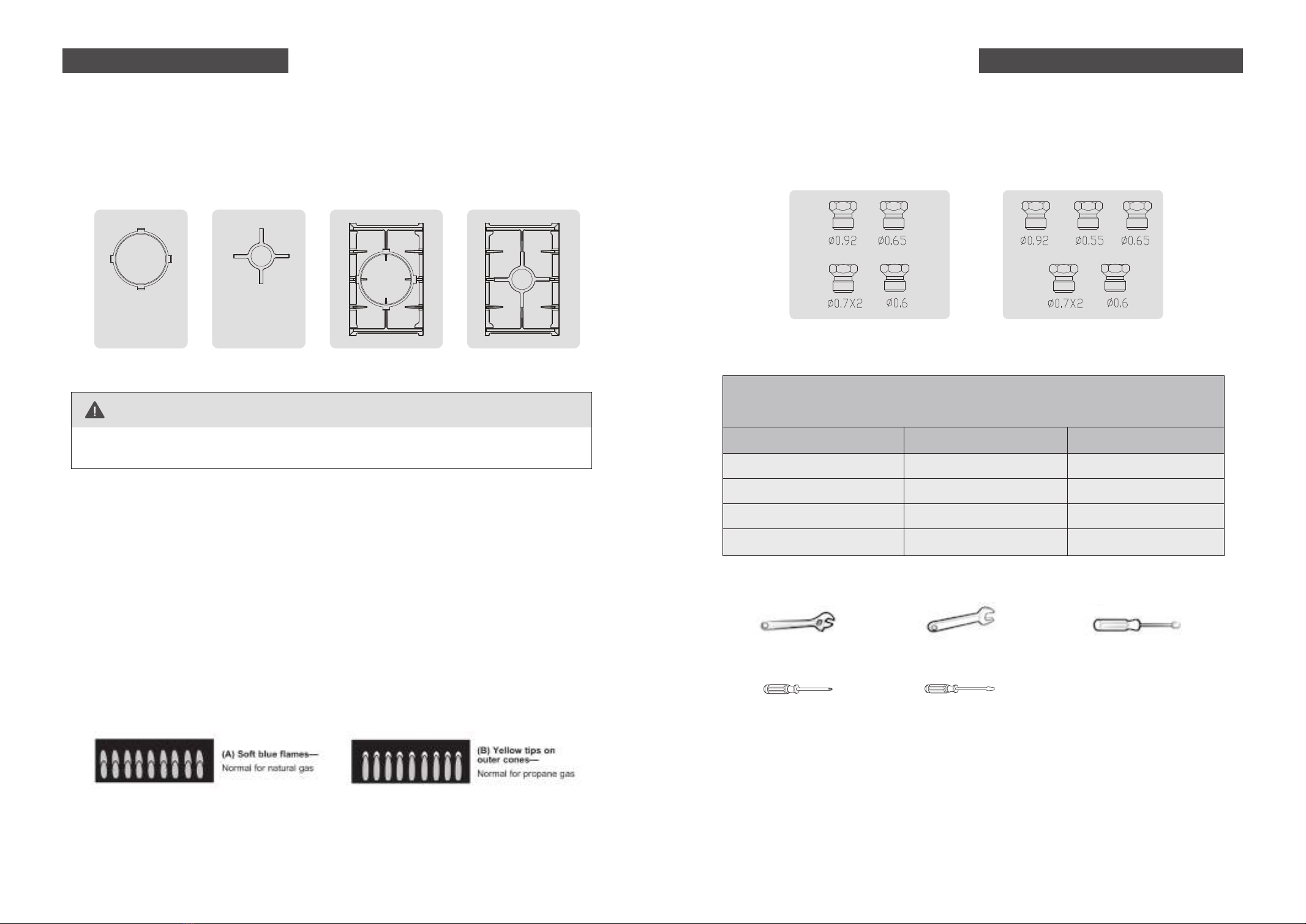
All FOTILE gas cooktops are manufactured and shipped to be used with natural gas. The cooktop
are also shipped with LP Conversion Kits (a set of properly-sized burner orifices, the pressure
regulator could use for both natural gas and LP), so the cooktop can be converted to be used with LP
gas. Please follow instruction when converting.
LP Conversion Kits
Ŗ!Requipped tools
1. Disconnect electrical power to the cooktop. Unplug the cooktop power cord, trip the circuit
breaker, or remove the fuse from the fuse box.
2. Shut off the gas supply to the cooktop. Close the manual shut-off valve to the cooktop.
To convert your cooktop for use with LP gas, perform the following steps
and procedures:
LP Conversion Instructions
Check the ignition
• This appliance is equipped with an electronic ignition device. Simply press the knob down-
ward and turn it counterclockwise to HI. Then, you will hear clicking sounds, which indicates
proper operation of the ignition system.
• Once air is purged from the supply line, the burner should light within 3-5 seconds, and the
clicking sounds will stop.
• After the burner lights, rotate the knob to your desired position.
• Try each burner in succession until all burners have been checked.
Check the flame quality
• Determine the quality of flames visually. Normal burner flames should look like following 2
pictures.
• Long, bright yellow flames are not normal. Normal flames may show signs of an orange tint
when well heated or signs of flickering orange due to particles in the gas or air.
Installation instructions
BURNER BTU RATE Orifice size [mm]
BURNER ORIFICE SIZES AND OUTPUT RATINGS
(LP Gas [Propane] 10 in WCP)
Versatile Tri-Ring Burner
Semi Rapid Burner
Simmer Burner
Rapid Burner
15000
4500
3000
9100
In:0.6/Out:0.7(2 pcs)
0.65
0.55
0.92
Adjustable wrench 9/32” open-end wrench Nut drivers:9/32”or 7mm
Phillips screwdriver 3/16” Flat-blade screwdriver
Woks are often used for stir-frying and pan frying. To use a Wok, you need to attach the Wok
Grate so your Wok will sit on the burner properly and safely.The tea kettle grate is usually used
for small pans smaller than 6in.
1.the wok grate and the tea kettle grate can only be placed on the versatile tri-Ring burner cook-
ing grate,or the rapid burner cooking grate
2. Do not use both the wok grate and the tea kettle grate on the same burner.
Ŗ!Wok Grate & Tea Kettle Grate
Wok Grate Tea Kettle Grate Nozzles for LPG (5)
GLG30301
Nozzles for LPG (6)
GLG30401-Y/GLG30401
Questo manuale è adatto per i seguenti modelli
2
Indice
Lingue:
Altri manuali FOTILE Piano cottura