FSI F-DI25HP0105CM Guida rapida
FSI® 2.5/5 Ton AC/Heat Pump Units (ECU)
Operaonal Guide for
F‐DI25HP0105CM F‐DI35HP0100CM
F-DI40HP0100CM F-DI50HP0100CM
Operation guide for the FSI heat pump (ECU)
There are no user serviceable parts within the ECU and the user should not attempt to service the ECU in anyway.
Failure to use a grounded electrical outlet could result in an electrocution injury.
Disconnect unit from electrical outlet before performing any service or maintenance.
A qualified service facility or technician should only carry out any service that the ECU requires.
The ECU has very high operating pressures, moving parts and high electrical voltages and
current that can do bodily injury or can kill an untrained person, all warning labels should be
read and complied with.
Basic setup
Position the ECU in the required location to allow for the supplied ducting to be connected to the
shelter and the installation of the power supply and control cabling. There should be adequate
clearance on all sides of the ECU to allow for adequate airflow around the ECU to aid in proper
operation, a minimum of 2 feet on all sides should be maintained.
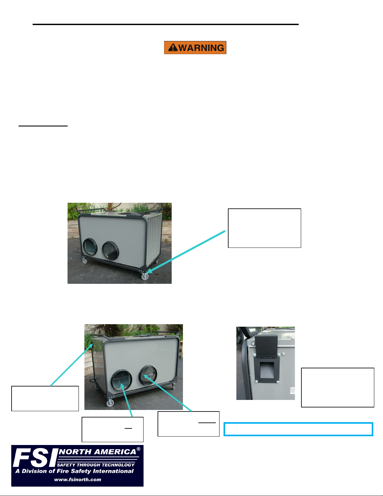
Lock the wheel brakes so the ECU will not roll away on a slight incline. The ECU is best positioned
on level even ground to allow for proper drainage of condensation removed during the cooling cycle.
Wheel brakes are
located on the
swivel wheel.
311 Abbe Road. Sheffield Lake, Ohio 44054
Phone: 440-949-2400
Fax: 440-949-2900
See us on the web at www.fsinorth.com
Install the ducting to and from the shelter and fasten with the integrated clamps. Slide the ducting
over the rings and using a screwdriver or nut driver tighten the integral band clamps on the rings.
The left duct is the outlet air from the ECU, supply air to the shelter, and the right duct is the
return air from the shelter. Attach to your shelter using the shelter manufacturer’s instructions.
Controller cable
rain shield
Air supply to
the shelter
Air return from
the shelter
Controller cable
plugged into ECU
under rain shield
Approx. outdoor noise level rating is 76db
5 Ton ECU’s require a minimum circuit capable of 50 amps if wired to a building supply and 2.5 ton
ECU’s require a minimum 30 amp circuit for starting purposes. The ECU will draw less current when
it is operating but needs the additional current for starting.
If the ECU has the optional resistance heater installed you will need to provide enough power to
operate the heater in cold weather. An example would be a 10kw heater installed. This will draw an
additional 42 amps at 240 volts or 37 amps at 208 volts this is usually wired as a separate power
cable and plug and will need it’s own power supply receptacle. In climates were the temperature falls
below 30 degree F it will be desirable to have the resistance heat. Simply plug in the second power
cord and it’s operation will be seamless to the shelter occupants. The resistance heater is controlled
by the controller/ECU and is transparent to the user. If it is not plugged in it will not operate nor add
any additional load.
Before plugging in the power cabling, verify that the circuit breaker is in the off position. Plug the ECU
power cable into either a line power source or an appropriate generator, if resistance heat is installed
and needed, plug in the additional power cord.
Turn on the circuit breaker.
The ECU’s fan will immediately start to circulate the air within the shelter, but no heating or cooling
will be enabled until the controller is turned on.
Controller setting
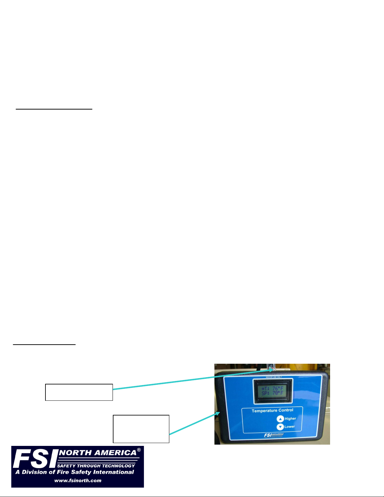
The controllers will self-test and then display the status of the temperature in the shelter on the top
line of the display. (All temperatures are in Fahrenheit)
Controller cable
Temperature
sensor
311 Abbe Road. Sheffield Lake, Ohio 44054
Phone: 440-949-2400
Fax: 440-949-2900
See us on the web at www.fsinorth.com
Route the controller cable into the shelter, one end plugs into the top of the controller and the other
end plugs into the ECU. The ECU has a rain shield cover over the control cable jack, lift the cover and
align the plug so that it can be inserted into the jack, you may hear a click when it locks in place. Low-
er the rain shield over the cable.
Install the controller in an appropriate location inside the shelter, on a desk, ledge etc. or hang it from
an appropriate location. Plug the control cable into the jack on the top of the controller box.
The controller should not be in a direct draft nor should it be located in an area that does not receive a
flow of conditioned air. Centrally located in an open area is the best place for even heat and cooling.
The power supply should be a 208 to 240 volt single phase supply. Do not run on any other power
sources. The supply power should be adequately grounded to avoid electrical shocks or the possibility
of electrocution.
Powering up the ECU

The second line of the display is the set point, this is the temperature that you set for your
requirements.
Press the Higher or Lower arrows once and the display will show set point and the temperature
that is currently set.
To change the temperature continue pressing or hold the up and down arrows and set your new
temperature.
When you are finished adjusting the temperature, and no changes are made for 2 seconds the
new temperature setting will lock in and the display will revert to the normal standard display.
An asterisk will show in the display to signify that the controller is ON. While the asterisk is
displayed the controller is actively operating the ECU compressor and/or optional electric
resistance heat.
Any adjustments of temperature setting can be done while the controller is operating by just
pressing the Higher or Lower button once and make your required changes as outlined above.
The controller will start to control the shelter temperature by cycling the ECU thru its heating and
cooling modes to maintain the desired setting regardless of whether it needs to heat or cool. The
controller is designed to try and maintain the temperature within 2 degrees of the set point chosen
without having to switch between heating or cooling modes.
Basic operation of the ECU
Initially there will be a (5) five-minute delay from the time power is supplied to the ECU and the
ECU will be able to start heating or cooling. This is not adjustable and is a mandatory period
required between cycles to insure that the internal pressures can equalize before the ECU
attempts to start.
There is a (5) five-minute delay built into the operating program to allow the unit to equalize
pressures before it does a restart. This is normal operation. The ECU will cycle on and off to
maintain the set temperature. During startup in a warm humid condition it may require a significant
amount of time for the ECU to reach the desired temperature. The ECU will dehumidify the space
first, and then lower the temperature second.
The ECU during it’s heating mode at certain outside temperatures will develop frost and ice on the
outside coils. In order to maintain the optimum conditions for heating the ECU will automatically go
into a defrost mode. The defrost mode may last as long as 15 minutes and during this time there
will be a lack of heat supplied to the shelter. This is normal operation and immediately upon
completion of the defrost cycle the unit will again go back to normal mode and start to supply heat
to the shelter. If the ECU has optional additional resistance heaters they will continue to supply
heat during a defrost cycle.
The fan is constantly ON to allow a better air mix of heating and cooling to help avoid uneven
cooling or heating of the shelter when the compressor unit cycles off.
311 Abbe Road. Sheffield Lake, Ohio 44054
Phone: 440-949-2400
Fax: 440-949-2900
See us on the web at www.fsinorth.com

Shut down procedure.
Turn the controller off by simply unplug it from the control cable.
If the ECU compressor was running it will stop. The ECU fan will continue to circulate air until it is
turned of at the power supply breaker. This is normal operation.
Turn off the power supply breaker.
Remove the plug from the power source.
Remove the ducting and controller cable from the ECU.
Clean and store the ducting, controller and ECU unit.
Storage of the ECU is best in a clean dry location.
311 Abbe Road. Sheffield Lake, Ohio 44054
Phone: 440-949-2400
Fax: 440-949-2900
See us on the web at www.fsinorth.com
ECU Set Up:
1. Position ECU next to tent with supply/return duct connections facing tent supply/return boots.
Make sure it is on a level surface.
2. Run Power Cord to Power Source. DO NOT CONNECT.
3. Connect PVC Supply Duct to ECU. This provides the conditioned air to the shelter. Connect to
air plenum if applicable.
4. Connect PVC Return Duct to ECU - This brings the air back from the shelter. Make sure return
duct is not blocked by anything inside the tent.
5. Position/Hang Remote Temperature Controller inside tent. Make sure RTC will not be in the
direct air flow from tent air plenum. Connect controller cable to controller. Run controller cable
thru the tent duct boot and connect to the ECU.
6. Connect Power Cable to Power Source. Take special care to make sure the breaker on the
power source is in the OFF position prior to connect ECU power cable.
7. Switch breaker to the ON position.
8. The ECU has a 5 minute delay before it will engage the compressor and start conditioning the
air inside your shelter or space. You will hear and feel the fan start to blow air. This will let you
know that the ECU has power to it. Make sure to check the remote temperature controller for
the asterisk which will indicate that the system is powered and the ECU is in good working
order. Finally set the temperature to the desired setting and wait for the ECU compressor to
start and the evaporator fan to start turning. Manually adjust the RTC for desired temperature.
ECU Shut Down:
1. Power the ECU down by switching the breaker at the power source to the off position.
2. Disconnect the power cord from the power source. Take special care to make sure that the
power source is turned off or shut down prior to disconnecting the ECU power cable. Wrap
power cable around the ECU push handle for storage.
3. Disconnect the remote temperature controller and return it to its storage case. Store the remote
temperature cable in the case as well.
4. Disconnect the PVC ducting from the shelter then from the ECU. You may want to keep it
stretched out on the ground so it has a few minutes to dry before storing it.
5. Store ECU in a clean dry area. Adding a cover will help keep dust and debris from entering the
condenser fan area.
ECU “QUICK SET UP / SHUT DOWN

Warranty
Limited Parts Warranty
The manufacturer warrants to the original purchaser / user that the above-described unit shall be operational
and free of defects at the time of delivery.
The warranty covers normal parts replacement for a period of (12) twelve months.
The warranty is dependant on good operational practices of the owner and operation of the unit in accordance
with the above operational manual information.
Parts can be pre ordered and purchased, but will not be credited until the manufacturer or his designated agent
returns said parts for inspection and deemed to be defective.
This warrant does not cover labor costs, shipping costs or associated customs duties or other miscellaneous
costs incurred in the removal or replacement of the defective parts and does not cover for consequential
damages that may or may not have occurred due to a defective part or unit failure.
The foregoing warranty is in lieu of all other warranties, express or implied, including those of merchantability or
fitness for any purpose not expressly set forth herein. No affirmation of Manufacturer, by words or action, other
than as set forth in this Section shall constitute a warranty. Manufacturer warranty does not apply to any Goods
which have been subjected to misuse, mishandling, misapplication, neglect (including but not limited to
improper maintenance), accident, improper installation, modification (including but not limited to use of
unauthorized parts or attachments), or adjustment or repair performed by anyone other than Manufacturer or
one of Manufacturers authorized agents. When returning products to Manufacturer, packaging must be ad-
equate or all warranty is null and void. Buyer will pay for the cost of Shipping to the Manufacturer for all war-
ranty repairs.
For warranty replacements contact your original equipment supplier for a return merchandise authorization
number (RMA#) to expedite the claim process.
Any parts or equipment shipped without an RMA# will be refused by the Manufacturer and returned to the
shipper.
311 Abbe Road. Sheffield Lake, Ohio 44054
Phone: 440-949-2400
Fax: 440-949-2900
See us on the web at www.fsinorth.com
ECU Trouble Shooting:
1. The ECU will not run. - Check electrical connections, power cord, Temp controller cable, etc.
2. The ECU is operational (condenser fan running) but not providing cold/hot air from the supply
ducting. Have an authorized HVAC technician examine the unit.
3. The ECU compressor won’t engage. Check your power source; make sure you have the
appropriate power connect to the ECU. Check the power source; make sure you have a power
source capable of operating your ECU.
4. The ECU is icing up. Check that the supply and return ducts are installed correctly. The ducts
should be as straight as possible without hard bends or kinks. Check return air duct. Make sure
it is free of debris. Check tent air plenum. Make sure there are NO choke points or obstructions.
Check to make sure the ECU is positioned on level ground.
5. Remote Temperature Controller won’t show set point/current temp correctly. Please the
controller in a cool dry area out of direct sunlight like a vehicle with AC running. Try and cool
the RTC.
6. Remote Temperature Controller does not have power. Check cable connections. Replace if
necessary.
Questo manuale è adatto per i seguenti modelli
3
Indice
Altri manuali FSI Pompa di calore

Manuali Pompa di calore popolari di altre marche


Mitsubishi Electric
Mitsubishi Electric PUZ-SWM60VAA Manuale utente

Dimplex
Dimplex LI 16I-TUR Guida utente

Carrier
Carrier WSHP Open v3 Guida rapida alla configurazione

TGM
TGM CTV14CN018A Manuale utente

Carrier
Carrier 38MGQ Series Manuale utente

Kokido
Kokido K2O K880BX/EU Guida alla risoluzione dei problemi


