FUHR multitronic 881 Manuale

Installation, operation and
maintenance instructions
These instructions are
to be passed on by the
fitter to the use
MBW20-GB/07.11-17
WWW.FUHR.DE
www.fuhr.dewww.fuhr.de

2WWW.FUHR.DE
1 Introduction 3
2 Important information/safety instructions 4
3 Delivery scope 5
4 Installation instructions 7
4.1 Routing and drilling operations 7
4.1.1 Cable-laying depending on the door design 8
4.1.2 Routing for the electronic drive unit in the door leaf 8
4.1.3 Routing for the tappet contacts in the door leaf 9
4.1.4 Routing for the control unit casing in the door frame 9
4.1.5 Routing for the switching power supply unit in the door frame 10
4.1.6 Drilling for the surface-contact device’s cable 10
4.1.7 Drilling for the 230 V power supply cable 11
4.1.8 Safety instructions 11
4.1.9 Screws for fixing individual components 11
4.2 Installation 12
4.2.1 Installation of the tappet contacts in the door leaf 13
4.2.2 Installation of the multipoint locking system in the door leaf 14
4.2.3 Installation of the cable guides, end caps and cover plates in the door leaf 15
4.2.4 Installation of the magnetic contact in the door frame 16
4.2.5 Installation of the surface-contact device in the door frame 16
4.2.6 Installation of the control unit casing in the door frame 17
4.2.7 Installation of the switching power supply unit (transformer) in the door frame 18
5 Commissioning 19
5.1 Fabricator’s function check 19
5.2 Commissioning on site 19
5.3 The radio keys (radio-controlled remote control) 20
5.4 Master radio key 20
5.5 Tuning in and deleting radio keys 21
5.5.1 Tuning in individual radio keys (max. 25) 21
5.5.2 Deleting individual radio keys (except the master key) 22
5.5.3 Deleting all radio keys (except the master key) 23
6 External connection options 24
6.1 Control unit casing circuit board 24
6.1.1 Application examples for circuit board assignment 26
6.2 The drive unit’s multi-functional jack 27
7 Maintenance and care 28
7.1 Contact device 29
8 Troubleshooting 30
8.1 Adjustment of strike plates/one-piece strike plates and latch changing 31
9 Technical data 32
9.1 FUHR multitronic radio key (remote control) 32
9.2 FUHR multitronic control unit with radio receiver 32
9.3 FUHR multitronic drive unit 32
9.4 FUHR multitronic switching power supply unit 33
10 Optional accessories 34
11 Wiring diagram 36
Contents
www.fuhr.dewww.fuhr.de
Instructions in further languages, refer to www.fuhr.de

3
The FUHR multipoint locking system multitronic 881 locks doors electromotively – at all times and fully automated.
•Particularly reliable – strong and fast – due to two parallel high performance drives.
•This conserves energy as the door always closes imperviously.
•Enables secure locking of main entrance doors, apartment doors or back doors.
•Suitable for use with all door materials.
•All locking components can be operated either electromotively via a radio key, mechanically via the profile cylinder’s key, or
from the inside via the door lever handle.
•The electricity and data transfer is carried out from the door frame to the door leaf via a wireless transmission device. Spring-
loaded contact pins enable the door leaf to be unhinged for e.g. for decorating purposes at any time.
The standard locking and unlocking functions in detail:
Special functions are described in chapter 6.
Locking (closing):
All locking components are locked automatically 3 sec. after the door has been closed over. (This can however in
emergency situations - e.g. in the event of power failure - also be carried out mechanically by turning the key 4 times.)
Unlocking (opening) from the outside:
•By means of the radio key provided
•Alternatively by using the free-running profile cylinder’s key (depending on the drive-gear position; 4 turns!)
•Optionally by means of another access system e.g. transponder, code lock, finger print recognition, eye scanner or similar
(release signal via potential-free contact!)
Unlocking (opening) from the inside:
•Via the door lever handle as usual
•Alternatively by using the free-running profile cylinder’s key (depending on the drive-gear position; 4 turns!)
•Alternatively by means of the radio key provided
•Optionally via a domestic intercom system (6-12 V AC!)
•Optionally via a wireless wall-mounted push-button switch
•Optionally by means of another access system e.g. transponder, code lock, finger print recognition, eye scanner or similar
(release signal via potential-free contact!)
•As well as access control systems pertaining to contemporary BMS devices (Building Management Systems) (24 V DC pro-
cessor impulse!)
The locked mode is indicated by two brief acoustic signals. Simultaneously a red LED located on the control unit on the internal
side of the door indicates the locked mode. A green LED indicates the unlocked mode.
Do not operate the lever-handle during the electrical locking and unlocking procedure!
Further electrical connections are available for:
•Alarm systems
•Access control systems (fingerprint scanner, code lock, transponder etc.)
•Illuminated fixed pad handles/glazed units
•Electrically operated door openers (e.g. for disabled accessible doors = ‘barrier-free building’)
1 Introduction
1 INTRODUCTION
2 IMPORTANT
INFORMATION
3 DELIVERY SCOPE
8 TROUBLE-
SHOOTING
4 INSTALLATION
INSTRUCTIONS
5 COMMISSIONING
6 EXTERNAL
CONNECTION
OPTIONS
7 MAINTENANCE
AND CARE
9 TECHNICAL
DATA
10 OPTIONAL
ACCESSORIES

4WWW.FUHR.DE
These instructions are aimed at door fabricators and contain important information regarding installation, commissioning and
operation pertaining to the FUHR multipoint locking system multitronic 881. Please read carefully prior to installation and com-
missioning. The points raised here provide supplementary information to the FUHR product information M3/3. The importance of
their compliance must be pointed out to builders and end-users. In the event of non-compliance with these imperative instructions,
faultless system operation cannot be warranted.
We assume that the installation as well as commissioning is carried out exclusively by professional staff.
Text passage denoting this symbol is relevant to safety and must be strictly adhered to.
The FUHR multipoint locking system multitronic 881 has been designed and manufactured taking safety-related regulations and
harmonised standards into account.
The safety of the FUHR multitronic product largely depends on its correct installation and regular
maintenance! The installation of the electronic components requires particular care, since abrasion points,
defective cables, damaged contacts, etc. affect security and can lead to the malfunction of the system. Please
ensure that all components are in perfect functioning condition prior to installation. Damaged or defective
components may not be used under any circumstances. Use the locking system only in technically
perfect condition! Malfunctions that impair security are to be eliminated immediately. Until the
malfunction has been eliminated, the drive unit is to be switched off and operated mechanically! The power
supply unit’s power feed is to be disconnected when working on the locking system and live components.
The FUHR multipoint locking system multitronic 881 has been engineered to be used in conjunction with the provided FUHR
multitronic components. We accept no liability for improperly installed systems and/or the use of non-original or non factory
approved system accessory parts. The modification of components or the use of non approved accessory components can cause
malfunctions. Material damage or personal injury resulting from non-compliance with the installation, operation and maintenance
instructions or inappropriate operation invalidates the warranty. We assume no liability for any consequential damage.
The FUHR multipoint locking system multitronic 881 must be protected from humidity. It is not suitable for areas with high humidity
and chemical substances.
The FUHR multipoint locking system multitronic 881 has been primarily designed for installation in main entrance doors,
apartment doors and back doors. The system with 2 hook bolts (type 3) has been tested and certified in accordance with
DIN EN 179. The variants with 2 round bolts (type 8) and with 2 hook and dual round bolts (type 11) have been tested and
certified in accordance with DIN EN 1125. For this purpose durability testing in the highest grade (grade 7) with 200,000
operations was carried out successfully.
When using in heavily frequented doors (more than 50 operations per day) e.g. in public or office building pro-
jects, it is necessary to use either of the two day-latch functions during busy periods (refer chapter 6.1).
All images, dimensions, product and design related information contained in these instructions represent the latest
developments regarding the FUHR multipoint locking system multitronic 881 at the time of printing. This product is subject to a CIP
(continuous improvement process) and is constantly enhanced to reflect the latest technology. For the purpose of your satisfaction,
we reserve the right to implement changes to this product. Model and product claims cannot be lodged.
The latest version of these instructions is published on our website www.fuhr.de.
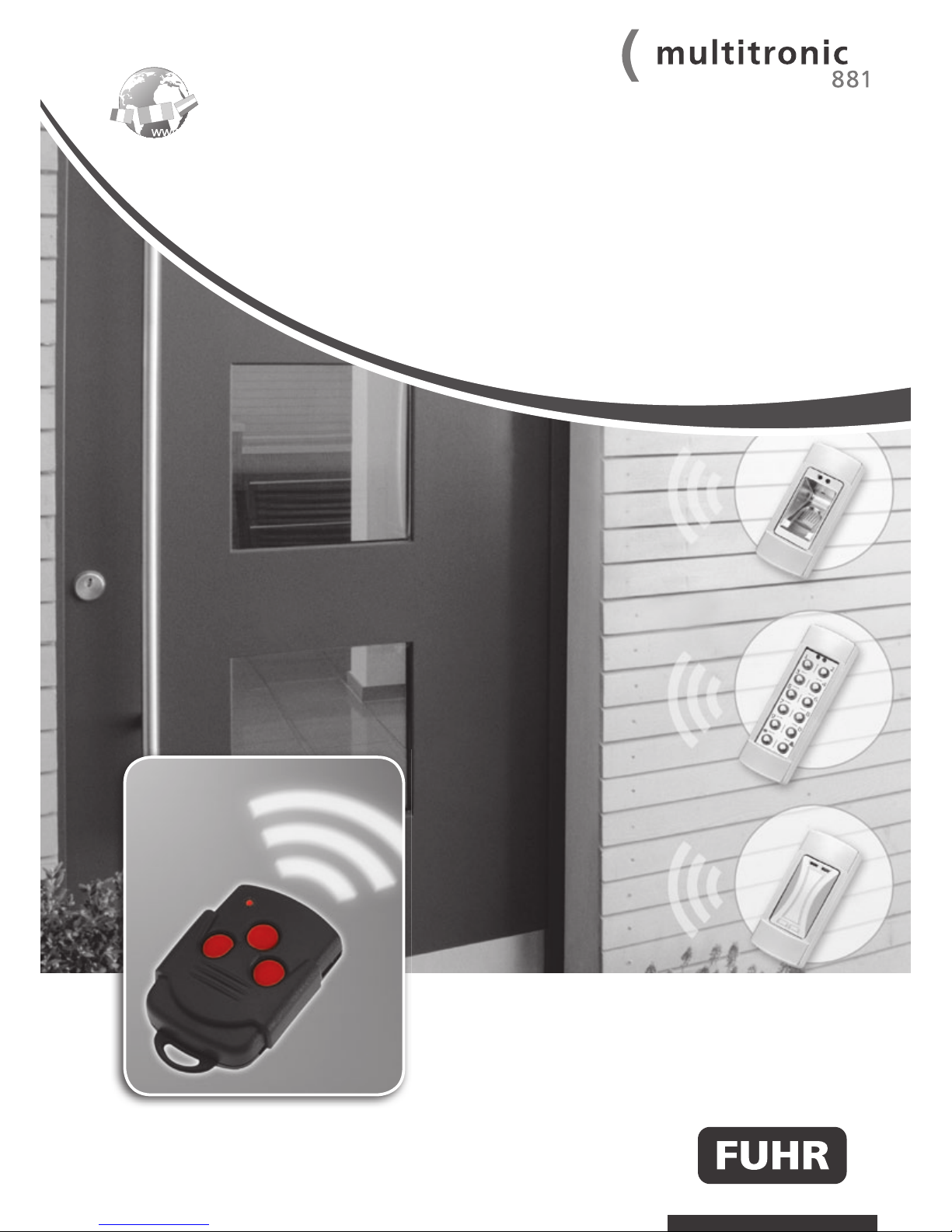
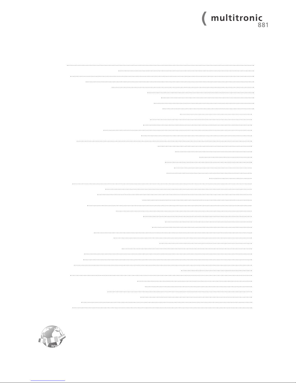
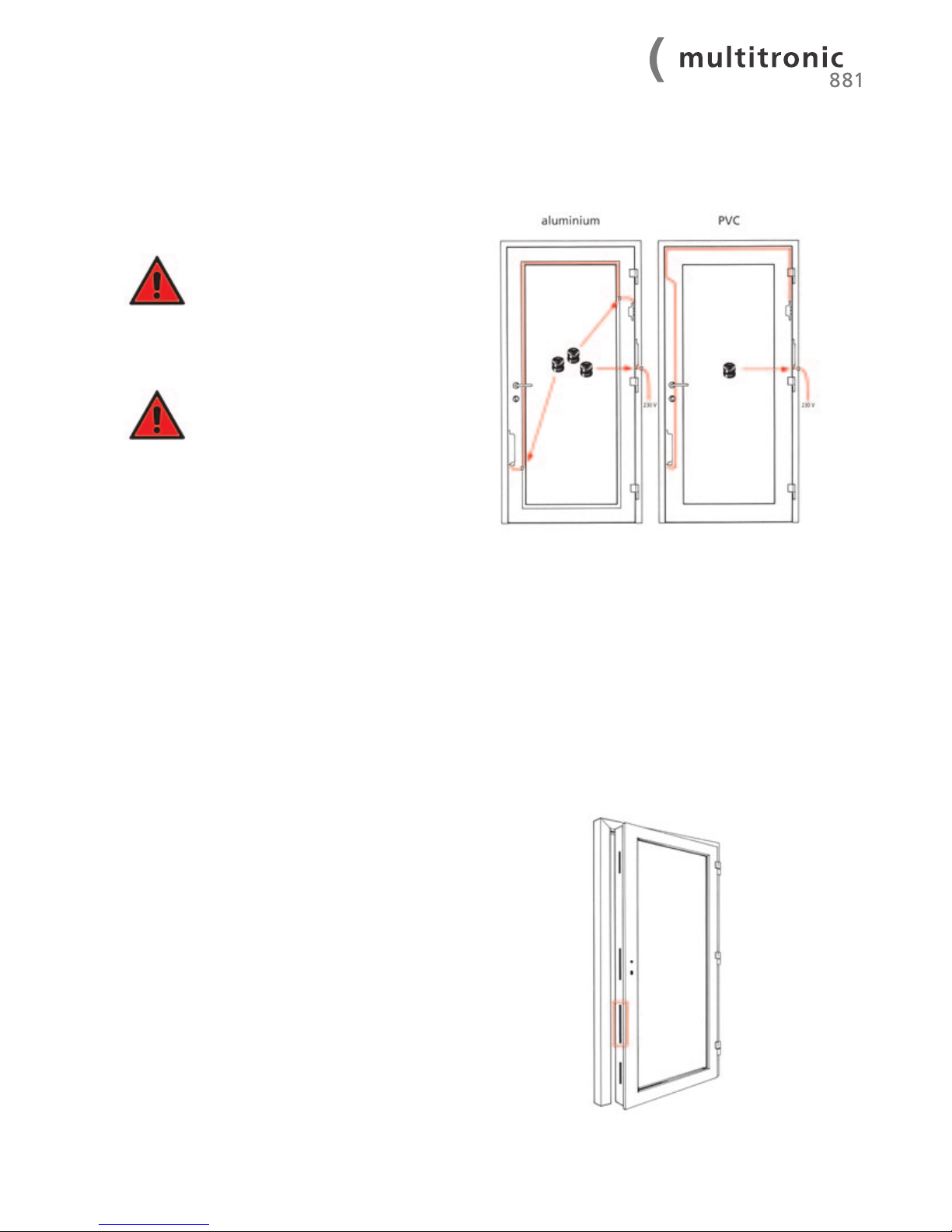
The installation steps depicted on the following pages serve as a schematic diagram. Due to the numerous profiles available on the
market, there may be slight deviations in specific points. It is therefore imperative that the profile-related routing drawing provided
with the FUHR multitronic set is adhered to. Please contact your sales partner or the manufacturer in the event of discrepancies or
queries.
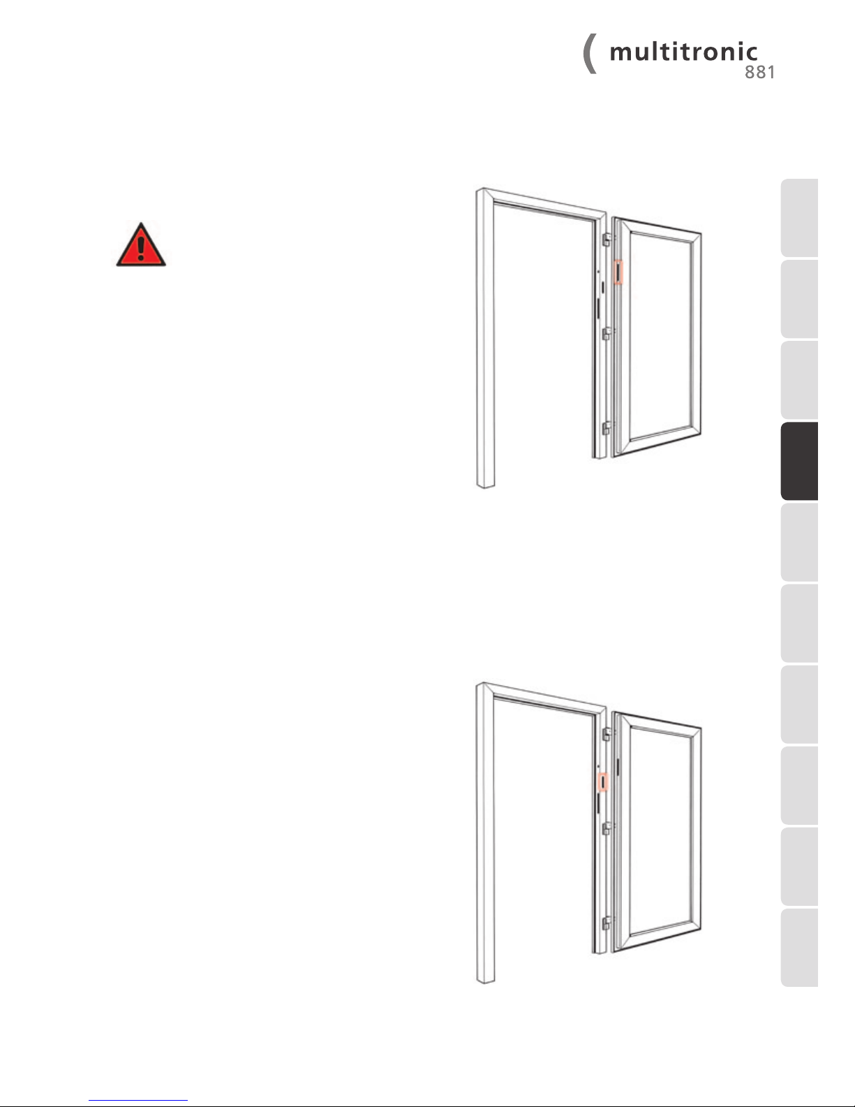
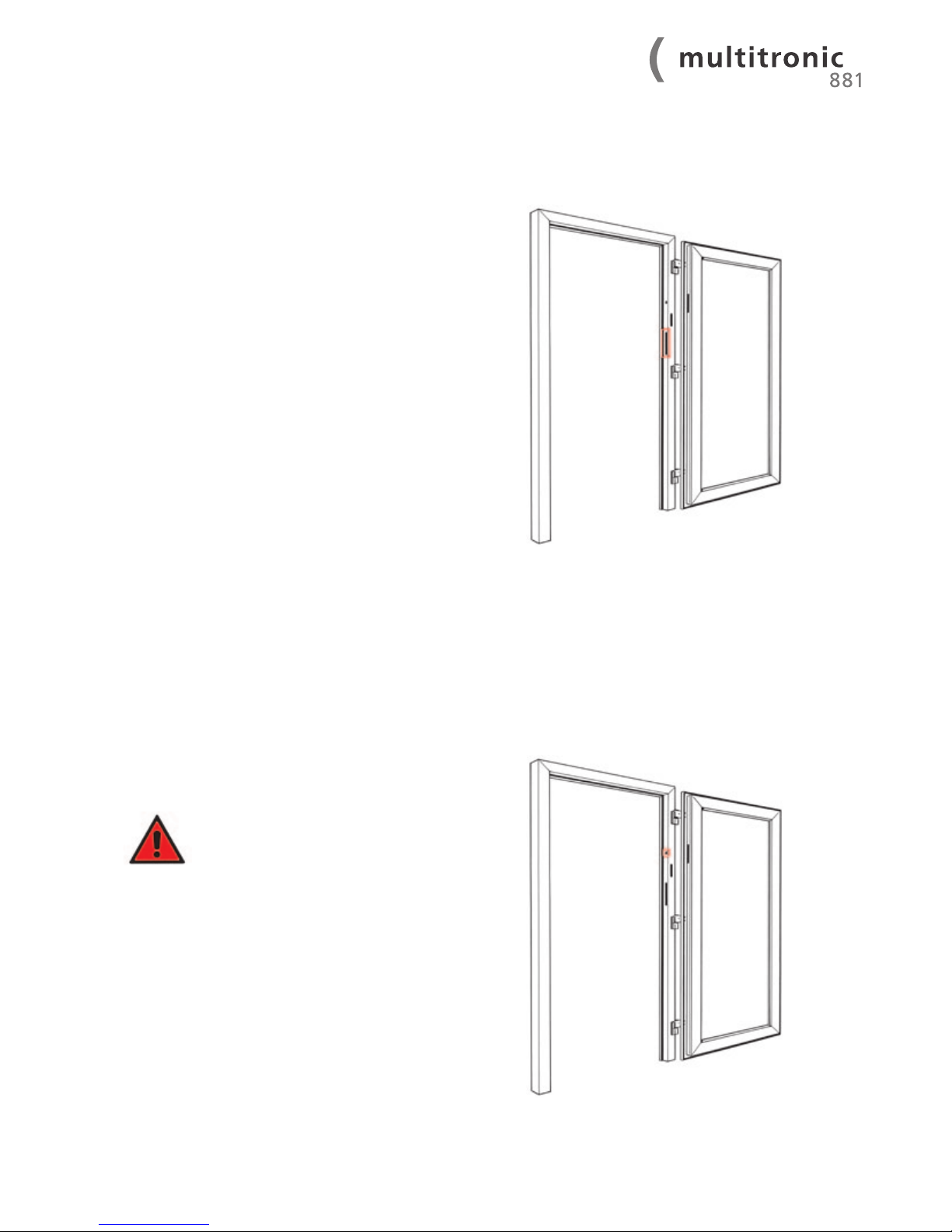
The indicated sequence in these installation instructions is exemplary. The sequence may be varied if required.
IMPORTANT!
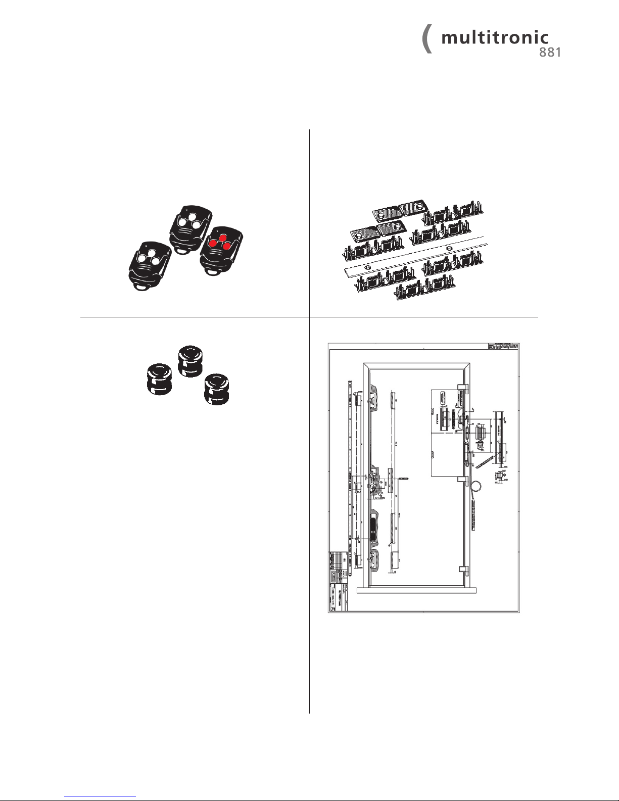
All components contained in the set (particularly the control unit and the radio key) are coordinated and should not be
used in conjunction with other sets.
2 Important information/safety instructions

5
One-piece keep or individual keeps
Profile related version,
incl. magnetic contact
Multipoint locking system multitronic 881
incl. electromotive drive unit
Control unit with radio receiver and visual locking
indicator
Preassembled cable connectors (length 200 and 300 mm)
Switching power supply unit (transformer)
Profile related version,
230 V AC input/12 V DC output, Cable connectors 230 V
(length 3000 mm - surface- mounted cable), earth/ground
cable (length 400 mm) and 12 V (length 200 mm)
preassembled
Surface-contact device for electricity and data transfer
Preassembled cable connector (length 250 mm)
Tappet contacts for electricity and data transfer
Cable connector (length 4000 mm), with preassembled
multi-functional jack
3 Delivery scope
1 INTRODUCTION
2 IMPORTANT
INFORMATION
3 DELIVERY SCOPE
8 TROUBLE-
SHOOTING
4 INSTALLATION
INSTRUCTIONS
5 COMMISSIONING
6 EXTERNAL
CONNECTION
OPTIONS
7 MAINTENANCE
AND CARE
9 TECHNICAL
DATA
10 OPTIONAL
ACCESSORIES

6WWW.FUHR.DE
Radio key
to be handed over to the end user;
3-channel radio key as remote control,
1 pc. with red buttons = master key
2 pcs. with turquoise buttons
Cover plate, cable guides and end caps
for safe cable-laying (only for doors with Euro groove);
2 m. cover plate
6 pcs. double cable guides
2 pcs. end caps
Cable protection sleeves
3 pcs.
Profile-related routing drawing

7
The routings for the FUHR multipoint locking system multitronic 881 are carried out in accordance with the routing drawing
provided.
In addition to the conventional routings
for FUHR multipoint locking sys-
tems, for example on multisafe 855,
only 2 additional routings in the door
leaf and the door frame are required.
These installation instructions there-
fore only describe the additional routing
and drilling operations for the electronic
locking mechanism.
4 Installation instructions
4.1 Routing and drilling operations
1 INTRODUCTION
2 IMPORTANT
INFORMATION
3 DELIVERY SCOPE
8 TROUBLE-
SHOOTING
4 INSTALLATION
INSTRUCTIONS
5 COMMISSIONING
6 EXTERNAL
CONNECTION
OPTIONS
7 MAINTENANCE
AND CARE
9 TECHNICAL
DATA
10 OPTIONAL
ACCESSORIES

8WWW.FUHR.DE
Version A – e.g. for PVC doors:
Cable-laying in the Euro groove.
Deburr the cable feedthrough hole
and insert the cable protection sleeves
provided.
Version B – e.g. for aluminium doors:
If the cable is to be laid in the glazing rebate’s Euro groove, a
Ø 10 mm drill hole is to be drilled in the glazing rebate area.
Deburr the cable feedthrough hole
and insert the cable protection sleeve
provided.
The 230 V electricity cable is a surface-mounted cable.
Conduit must be used for concealed cabling. The door
frame must be earthed/grounded.
The cable-laying for version A is described in the
following installation steps.
Routing in compliance with the separate routing drawing
between the main lock and the bottom additional locking
point
4.1.1 Cable-laying depending on the door design
4.1.2 Routing for the electronic drive unit in the door leaf

9
Routing in compliance with the separate routing drawing on
the hinge side of the door leaf
Make sure that the surface-contact device
and the tappet contact device are aligned
accurately horizontally. Refer to chapter
4.1.6.
Routing in compliance with the separate routing drawing on
the hinge side of the door frame face (on the inside of the
building)
4.1.3 Routing for the tappet contacts in the door leaf
4.1.4 Routing for the control unit casing in the door frame
1 INTRODUCTION
2 IMPORTANT
INFORMATION
3 DELIVERY SCOPE8 TROUBLE-
SHOOTING
4 INSTALLATION
INSTRUCTIONS
5 COMMISSIONING
6 EXTERNAL
CONNECTION
OPTIONS
7 MAINTENANCE
AND CARE
9 TECHNICAL
DATA
10 OPTIONAL
ACCESSORIES

10 WWW.FUHR.DE
Routing in compliance with the separate routing drawing on
the hinge side of the frame profile
Drilling in compliance with the separate routing drawing in
the frame profile, laterally at the same height as the tappet
contact device
Make sure that the surface-contact device
and the tappet contact device are aligned
accurately horizontally. Refer to chapter
4.1.3.
4.1.5 Routing for the switching power supply unit in the door frame
4.1.6 Drilling for the surface-contact device’s cable
Altri manuali per multitronic 881
2
Questo manuale è adatto per i seguenti modelli
1
Indice
Altri manuali FUHR Serratura della porta


