FunkTronic Major BOS V Series Manuale utente

Major BOS V(oIP)
Major BOS 1V
Major BOS 8V
Major BOS 4V

- 2 - mbosv_eng (25.02.2014)
mbosv_eng (25.02.2014) - 3 -
Contents
Connectivity 3
Major BOS 1V/4V/8V 3
Control and Display Elements 4
Layout - Major BOS 4V 5
Layout - Major BOS 8V 6
Calling Radio Channels 7
Encoder 8
Transmitter Control 8
Connection to Telephone AF 8
Microphone Selection 8
Opto-Coupler Input 9
Functions for TETRA Digital Radios 9
Configuration via the Web Interface 10
The Web Interface 11
The System Pages 12
The Application Pages 14
RS232 Monitor 17
Sockets Pinout 18
Technical Data 19
General Safety Remarks 20
Returning of Old Equipment 20
- 2 - mbosv_eng (25.02.2014)
mbosv_eng (25.02.2014) - 3 -
Major BOS 1V/4V/8V
Major BOS 1V, Major BOS 4V and Major BOS 8V are µC-controlled desktop controller
units for 2-way radio systems controlling one, up to four or eight radios, respectively.
The connection to the radios is achieved over one single ethernet connection (LAN
or via Internet) instead of separate cables for each radio circuit. The device can be
configured via its web interface using any PC that is connected to the same IP network.
For this, you can use an ordinary web browser (e.g. Firefox or Internet Explorer).
For operation a 12 V DC power supply is necessary. Alternatively, the Major can also be
ordered with the option Power-over-Ethernet (PoE), that allows power supply via the
ethernet socket (ETH).
A Major BOS 1V can control one, a Major BOS 4V can manage up to 4, a Major BOS
8V up to 8 channels (radio sets, PA systems -/intercom etc.) via their ethernet interfaces.
Furthermore, an external handset/headset, an external signalling device and a tape
recorder. Furthermore there is a RS232-connection, to which a terminal or PC can be
connected.
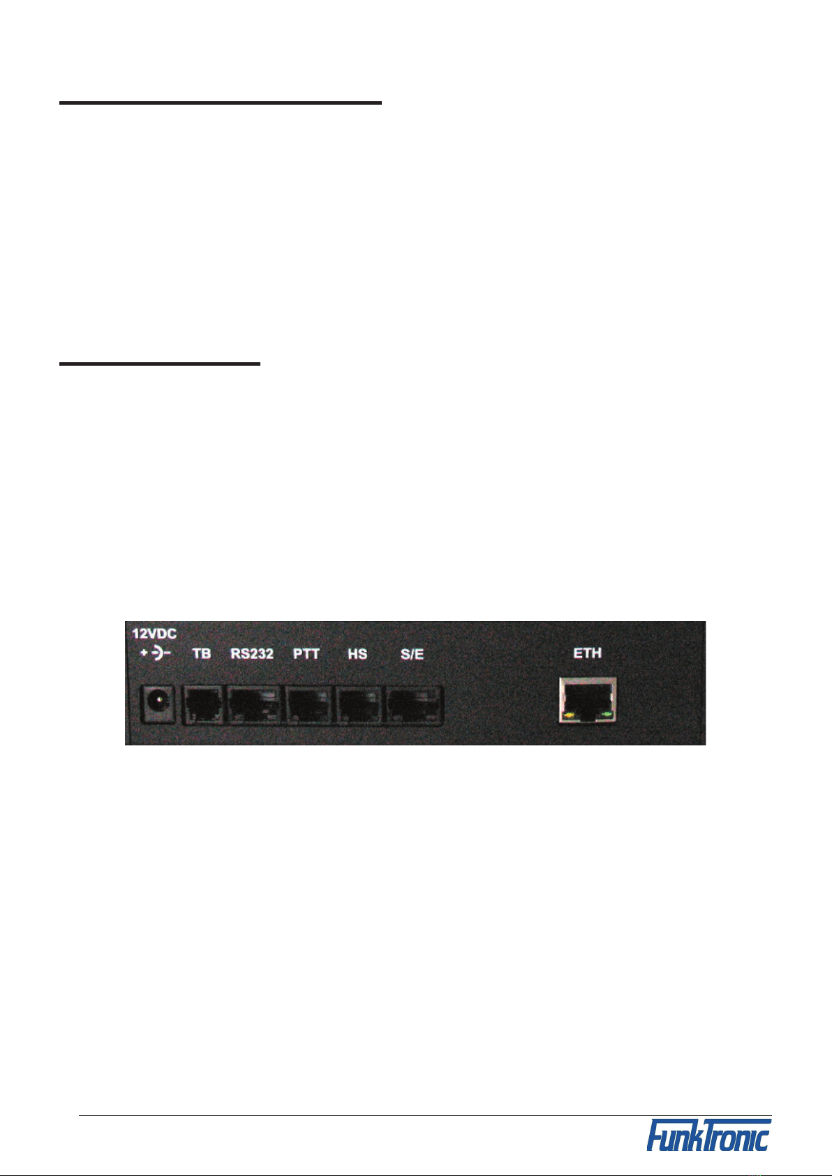
Connectivity
12VDC -> power supply connector (12V DC, external, max. 1.5A)
TB (ST7) -> tape recorder
RS232 (ST6) -> RS 232 connection
PTT (ST5) -> PTT (e.g. foot switch)
HS (ST4) -> headset
S/E (ST3) -> no function
ETH (ST1) -> ethernet interface
see also section Sockets Pinout

- 4 - mbosv_eng (25.02.2014)
mbosv_eng (25.02.2014) - 5 -
Control and Display Elements
Keyboard
The keyboard holds the following functions for each of the four/eight channels:
Button Function (standard)
(Funk-)kreis x selection button
VOL+ increase volume
VOL-
decrease volume
L / mute loudspeaker
S special function (not assigned, only MBOS 4V)
I / RUF1 button for tone call 1
II / RUF2 button for tone call 2
/ Senden PTT button
All buttons can be disabled separately. For Major BOS 1V, channel selection and loudspeaker
buttons are not necessary. The volume is adjusted by a potentiometer knob.
Carrier Display
For each of the four/eight circuits there is a separate carrier display (squelch) LED , that
is activated/deactivated using data telegrams.
PTT Display
For each of the eight circuits there is also a separate PTT display LED , that lights if the
transmitter for the respective circuit is keyed by pressing PTT, call 1 or call 2. (If a PTT
display flashes, another control set is transmitting on this radio circuit.)
Selection Display
The selection display LED lights, if the respective circuit was selected and is active. A
flashing selection display LED indicates that the Major is currently trying to establish the
connection via ethernet.
Loudspeaker / Volume Display (not for Major BOS 1V)
The volume display (separately for each channel) is an LED chain and indicates the current
volume. If the the loudspeaker is switched off, all LEDs of the chain are dark for Major
BOS 4V. The Major BOS 8V has a separate loudspeaker LED that displays the status of
the loudspeaker.

- 4 - mbosv_eng (25.02.2014)
mbosv_eng (25.02.2014) - 5 -
Layout - Major BOS 4V
1
4
5
6
8
7
9
2
3
10
11
1 - Transmiting- , Squelch- , Selection Status LED
2 - Channel Selection Buttons
3 - Volume Display (row of LEDs)
4 - Volume Control Buttons (+/
-
)
5 - Loudspeaker Buttons (mute)
6 - Special Function Buttons
7 - Encoder Buttons (I/II)
8 - PTT (for gooseneck or headset microphone)
9 - Loudspeaker
10 - PTT Button (for handset)
11 - Handset
12 - Gooseneck Microphone

- 6 - mbosv_eng (25.02.2014)
mbosv_eng (25.02.2014) - 7 -
Layout - Major BOS 8V
4
5
6
87
9
2
3
10
11
1
12
1 - PTT , carrier , loudspeaker and selection displays
2 - selection buttons
3 - volume buttons (increase)
4 - volume displays (LED line)
5 - volume buttons (decrease)
6 - loudspeaker buttons (mute)
7 - call 1 buttons
8 - call 2 buttons
9 - PTT buttons (for gooseneck microphone)
10 - loudspeaker
11 - handset with PTT button
12 - gooseneck microphone

- 6 - mbosv_eng (25.02.2014)
mbosv_eng (25.02.2014) - 7 -
Calling Radio Channels
Channel Selection
To activate one of the different channels push the corresponding selection button. To
deactivate a channel again push the corresponding selection button once more.
Depending on the configuration (see also: Configuration via the Web Interface) you
can either select several channels simultaneously or only one channel at a time. The
status of the loudspeaker can be set accordingly.
The channel selection display LED is illuminated if the channel is selected.
The channel selection at power-on can be configured via the Web Interface. The channel
selection during the last operation can also be saved for the next power-on.
Communicating with the Radio Subscriber
There are three different ways of talking to a radio subscriber:
a) By pushing one of the red PTT buttons the transmitter of the corresponding channel
is activated via a TCP telegram (PTT display LED lights up) and you can talk to the
caller through the gooseneck microphone. (It is also possible to connect an external switch
contact instead of a PTT button. See section Opto-Coupler input.) After pressing the
PTT button the caller can be heard on the loudspeaker. The receiver volume of the cor-
responding channel is adjustable.
b) By picking up the handset and pushing the PTT button on the inside of the handset. By
doing so the transmitter of the selected channel is activated (PTT LED lights up) and
you can talk with the caller through the microphone of the handset.
Depending on the configuration you can hear the caller constantly on the handset or only
after deactivating the PTT button. The call is ended by replacing the handset. The volume
of the earpiece and the microphone are each adjustable via the Web Interface.
c) By connecting a compatible headset and pressing the corresponding PTT button PTT2
(e.g. a foot switch). By doing this the transmitter of the selected radio channel is also
turned on (PTT LED lights up) and you can talk with the caller through the microphone
of the headset.
Depending on the configuration you can hear the caller constantly on the headset or only
after releasing the PTT button. The volume of the corresponding channel is adjustable.
The level settings for microphone, loudspeaker etc. can also be configured via the Web
interface.

- 8 - mbosv_eng (25.02.2014)
mbosv_eng (25.02.2014) - 9 -
Encoder
Major BOS V has an integrated encoder for call 1 and call 2. The calls for each channel
are transmitted directly with the corresponding buttons on the keyboard (I / RUF 1 or I /
RUF 2). The calls are transmitted as long as the corresponding button is being pressed.
Transmitter Control
The transmitters of the selected radio channels are activated with one of the PTT but-
tons (e.g. handset or headset) and stay activated as long as the PTT button is being
pressed. During transmission of call 1/2 the corresponding transmitters are automatically
activated.
It is always possible to transmit on non-activated radio channels by using the red PTT
buttons on the control panel. The assignments of the buttons to the channels can also be
customized (Web Interface).
Connection to Telephone AF
The audio-frequency connection is not integrated in the Major BOS V anymore. But by
connecting the external headset-adapter the headset can be used as a combined com-
municating device for telephone and radio.
The headset is switched to the telephone by an opto-coupler input, which has to be
configured accordingly.
Microphone Selection
For each of the 3 PTT inputs it is possible to program the corresponding microphone
individually via the Web Interface.
Additionally there are two ways of automatic headset detection:
- the Major BOS 8a can detect if a headset is connected by measuring the headset
supply voltage (see Web interface).
- one of the inputs can be configured as headset detection (headset is connected if
input is activated, i.e. connected to GND)
If the Major BOS 4a has detected a headset then all buttons programmed as SH/HS-
PTT use the headset microphone. Otherwise they use the gooseneck microphone.

- 8 - mbosv_eng (25.02.2014)
mbosv_eng (25.02.2014) - 9 -
Opto-Coupler Input
The opto-coupler input on ST5 can be configured via Web interface to fulfill different
tasks in the same way as all inputs can be.
To activate the opto-coupler input, a direct current (3V < U < 15V) is necessary that can
be obtained directly from ST14a/2. For higher ext. switching voltages an additional external
dropping resistor is necessary (internal dropping resistor = 1kohm).
Functions for TETRA Digital Radios
Using TETRA, speaking is not possible until the conversation is initiated. Therefor, the
radio transmits an attention tone. Usually, this tone cannot be heard in the loudspeaker
as it is muted when transmitting. Hence, the PTT button must be configured so that the
loudspeaker is not muted when it is pressed.

- 10 - mbosv_eng (25.02.2014)
mbosv_eng (25.02.2014) - 11 -
Configuration via the Web Interface
Preparing the PC
To be able to acces the Web Interface of the Major BOS V, a PC has to be configured
properly. Ex factory, the network address of the Major is as follows:
IP address: 192.168.16.181
Subnet mask: 255.255.255.0
The configuration of the network settings works similarly under Windows XP, Vista, 7 and
8. The following examples are for Win7. If you encounter any network problems, you might
have to contact your local network administrator. If you do not know the IP address of your
Major you can start it in "Default IP-Mode" (Major has the IP address as set ex factory).
Therefor, press the PTT button of channel 1 and the PTT button on the inside of the handset
while leaving the handset hung-up and switch on the Major (connect to power).
Open Control Panel (via the "Start" menu) and choose "View network status and tasks"
(via "Network and Internet"). On the following screen (see image above) click on "LAN
connection" (underlined red). On the next screen "LAN connection status", click on
"Properties" (you need administrator rights here), to get to the window "Properties of LAN
connection". Choose "TCP/IP(v4)" and again click on "Properties".
On screen "Properties of TCP/IP(v4)" choose "Advanced..." and click "Add..." in the IP
Questo manuale è adatto per i seguenti modelli
3
Indice
Altri manuali FunkTronic Controllori


