Garmin Force Manuale utente

FORCE®KRAKEN TROLLING MOTOR
INSTALLATION INSTRUCTIONS
Getting Started
WARNING
See the Important Safety and Product Information guide in the product box for product warnings and other
important information.
Failure to install this device according to these instructions could result in personal injury, damage to the vessel
or device, or poor product performance.
Failure to follow these warnings, cautions, and notices could result in personal injury, damage to the vessel or
device, or poor product performance.
Do not run the motor when the propeller is out of the water. Contact with the rotating propeller may result in
severe injury.
Do not use the motor in areas where you or other people in the water may come into contact with the rotating
propeller.
Always disconnect the motor from the battery before cleaning or servicing the propeller to avoid injury.
CAUTION
For the best possible performance and to avoid potential injury, damage to the device, or damage to your vessel,
installation by a qualified marine installer is recommended.
To avoid possible personal injury, always wear safety goggles, ear protection, and a dust mask when drilling,
cutting, or sanding.
When stowing or deploying the motor, be aware of the risk of entrapment or pinching from moving parts, which
can result in injury.
When stowing or deploying the motor, be aware of slick surfaces around the motor. Slipping when stowing or
deploying the motor may result in injury.
NOTICE
When drilling or cutting, always check what is on the opposite side of the surface to avoid damaging the vessel.
Tools and Supplies Needed
• Drill and a 5/16in. (8mm) drill bit
• #2 Phillips screwdriver
• 4mm hex bit or wrench
•9/16in. (14mm) socket
• Torque wrench
• Circuit breaker rated for continuous 60A
• Trolling motor plug and receptacle rated for 60A or greater (optional)
• 6, 4, or 2AWG (16, 25, or 35mm2) wire for extended runs of the power cable
• Solder and heat-shrink tubing, if extending the power cable
• Stainless steel pan head 1/4-20 (M6x1) bolts (if the included bolts are not long enough to mount the motor to
the deck)
TA-2019/5242
TA-2019/5243
TA-2019/5244
GUID-09FCEEF1-A8CD-4B9C-8A62-161A75852017 v1June 2023

Installation Preparation
Device Overview
Shaft cap
Power and transducer cables
Depth-adjustment collar
Steering system
Mount
Shaft
Propeller drive motor
2
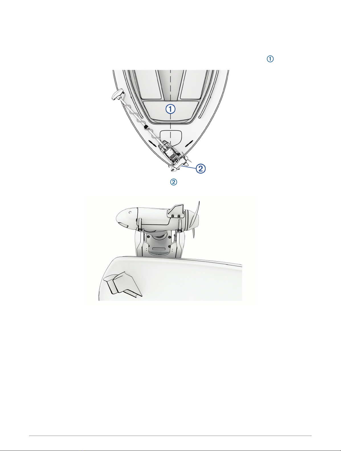
Mounting Considerations
When selecting a mounting location, observe these considerations.
• You must install the motor on the bow of your boat.
• You should install the mount so the deployed motor is as close to the centerline of the boat as possible.
• You must install the mount with the top of the cutout overhanging the gunwale of the boat. The U shape
should extend over the side of the boat.
• The motor secures to the deck of the boat using bolts, so you must have room to secure the mount from the
underside using washers and nuts.
• The motor must have clearance to move from the deployed to the stowed position and back again, so the
installation location must be clear of obstacles.
• Verify that the deck is strong enough for the weight and force of the trolling motor. Use a backing plate or
reinforce the boat if needed.
3
Connection Considerations
When making the wiring connections, observe the following considerations.
• You must connect the trolling motor to a 24or 36Vdc battery bank capable of supplying 60A continuously.
• You must connect to the power source through a circuit breaker rated for continuous 60A (not included).
• If necessary, you can extend the power cable using the appropriate wire gauge based on the length of the
extension (Power Cable Extension, page7).
• For convenience, you can install a trolling motor plug and receptacle rated for 60A or greater (not included)
in the bulkhead to make it easier to disconnect the motor from the power source.
Installation Procedures
NOTICE
When assembling the motor, you must use hand tools to install all of the parts, observing the torque
specifications when provided. Using power tools to assemble the motor may damage the components, and
voids the warranty.
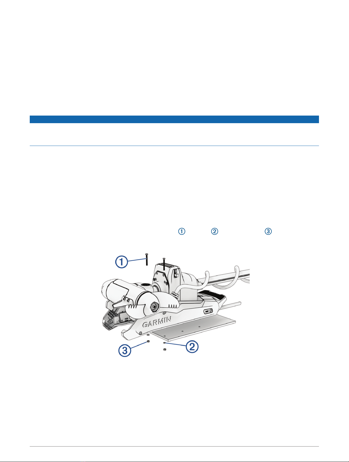
Installing the Motor on the Deck
NOTE: If the supplied bolts are not long enough for the mounting surface, you must obtain the appropriate
length stainless steel pan head 1/4 in. -20 (M6x1) bolts.
1Select a mounting location on the bow of your boat, according to the mounting considerations.
2Place the included mounting template on the mounting location with the mount on the template overhanging
the gunwale or the edge of the boat deck.
3Mark the mounting hole locations on the boat deck.
4Using a 5/16in. (8mm) drill bit, drill the mounting holes.
5Place the motor on the boat deck, aligning the holes on the mount with the mounting holes.
6Secure the mount to the deck using the included bolts , washers , and locking nuts in the two holes
closest to the gunwale or edge of the boat deck.
7Adjust the depth stop so that the motor can deploy without hitting the ground.
4
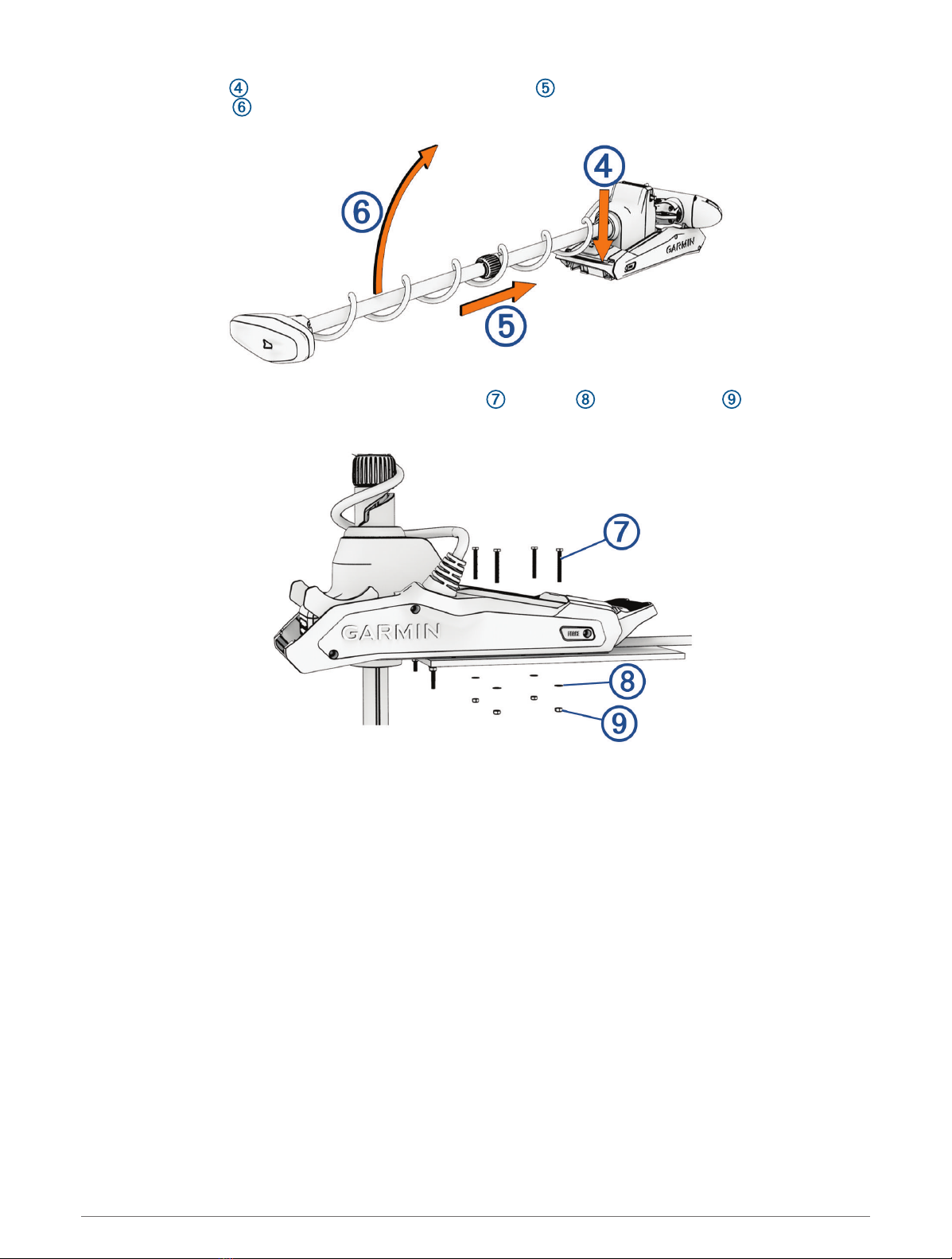
8Press the release , slide the propeller drive motor head out , and gently pivot the trolling motor into the
deployed position .
9Secure the mount to the deck using the included bolts , washers , and locking nuts in the remaining
holes.
10 Tighten the nuts to a torque of 10.85N-m (8lbf-ft.).
5
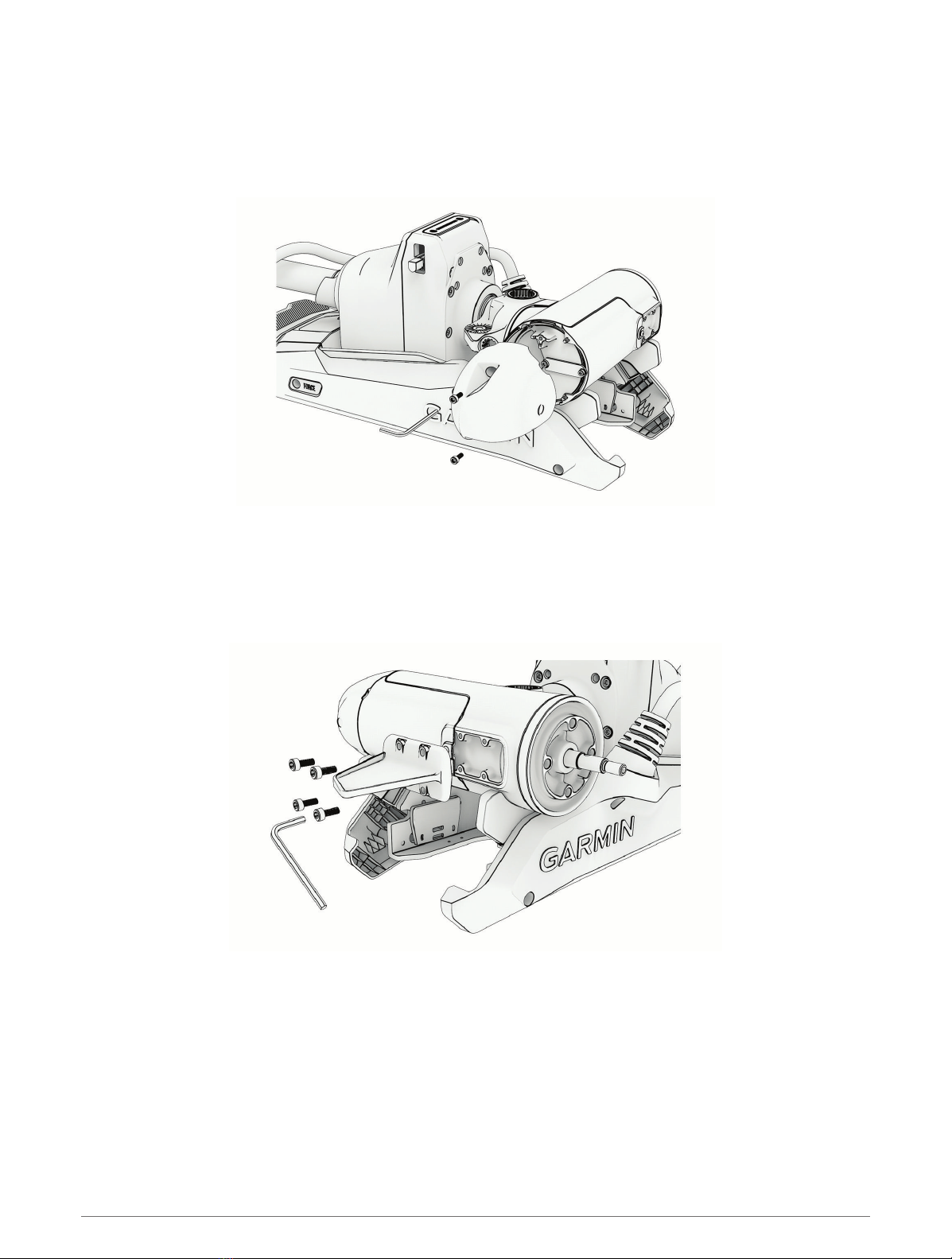
Installing the Nose Cone
NOTE: Most models come fully assembled. This procedure is only required for the 90-inch Force Kraken Trolling
Motor.
Using a 4mm hex bit or wrench, secure the nose cone to the front of the propeller drive motor using the two
included screws, ensuring the tab is on the bottom.
Installing the Skeg
NOTE: Most models come fully assembled. This procedure is only required for the 90-inch Force Kraken Trolling
Motor.
Using a 4mm hex bit or wrench, secure the skeg to the propeller drive motor using the four included screws,
ensuring the longer end of the skeg faces the propeller side.
6
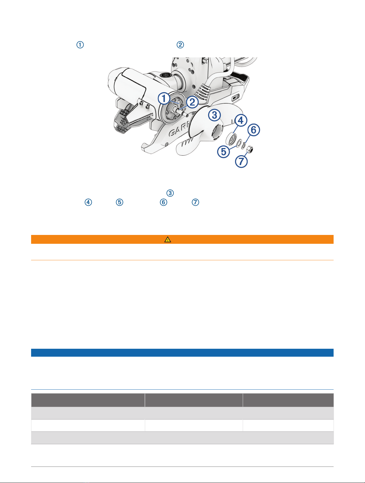
Installing the Propeller
1Insert the pin through the propeller motor shaft .
2If necessary, rotate the motor shaft to orient the pin horizontally so it is less likely to fall out during
installation.
3Align the channel on the inside of the propeller with the pin, and slide the propeller onto the motor shaft.
4Place the anode , washer , lock washer , and nut onto the end of the motor shaft.
5Using a 9/16in. (14mm) socket, tighten the lock nut to 6lbf-ft (8.13N-m) to secure the propeller.
Connecting to Power
WARNING
To avoid possible personal injury or property damage, the circuit breaker must be in the off position before you
connect the power cables from the trolling motor.
1Route the power cable to the breaker panel or the location where you plan to install the breaker.
2If necessary, extend the power cable using the appropriate wire gauge based on the length of the extension
(Power Cable Extension, page7) using solder and heat-shrink tubing.
3Install a trolling motor plug and receptacle rated for 60A or greater where the power cable enters a bulkhead
(optional).
4Connect the power cable to a circuit breaker rated for 60A (continuous).
5If necessary, connect the circuit breaker to a 60A, 24 or 36Vdc power source.
Power Cable Extension
You can extend the power cable using the appropriate gauge of wire based on the length of the extension.
NOTICE
Power cable extensions must use single-conductor wire, with a minimum 75°C (167°F) insulation, that is not
bundled, not sheathed, and not run through conduit. If you are using wire with 105°C (221°F) insulation or better,
you can bundle up to three conductors inside a sheath or conduit outside of engine spaces.
When installing the power cable extension, you must follow industry standards and best practices.
Extension length Minimum wire gauge Optimal wire gauge
0 to 3m (0 to 10ft. ) 6AWG (16mm2) 6AWG (16mm2)
3 to 4.6m (10 to 20ft.) 6AWG (16mm2) 4AWG (25mm2)
4.6 to 9.1m (20 to 30ft.) 6AWG (16mm2) 2AWG (35mm2)
7

Connecting the Transducer to a Chartplotter
Select Force Kraken Trolling Motor models include a built-in transducer. If your model does not include a
transducer, you must install one before you can connect it to a compatible chartplotter.The built-in 12-pin
transducer is compatible with select Garmin® chartplotter models. Go to garmin.com or contact your Garmin
dealer for more information.
1Route the transducer cable to the installed chartplotter. If necessary, connect the included extension cable or
a longer extension cable.
2Install the locking collar on the end of the transducer cable.
3Connect the transducer cable to the transducer port on the back of the chartplotter.
You can refer to the instructions provided with your chartplotter to identify the transducer port.
Stabilizer Installation
The stabilizer is an optional accessory that can help stabilize and provide additional support for the trolling
motor when it is in the stowed position.
NOTE: A stabilizer is only included with the Force Kraken Trolling Motor 90" model.
Installation instructions for the stabilizer are provided in the stabilizer box.
Remote Control Installation
The remote control connects to the trolling motor wirelessly and is paired at the factory.
Operation instructions are included in the Force Kraken Trolling Motor Quick Start Manual.
Maintenance Needs and Schedule
NOTICE
After using the motor in salt water or brackish water, you must rinse off the entire motor with fresh water, and
apply a water-based silicone spray using a soft cloth. You should avoid spraying jets of water at the cap on the
top of the shaft when rinsing the motor.
To maintain your warranty, you must perform a series of routine maintenance tasks as you prepare your motor
for the season. If you use or transport the motor in dry, dusty environments (traveling on gravel roads, for
example) you should perform these tasks more often during the season.
For detailed procedures and information on service and replacement parts, go to garmin.com/manuals/kraken
_trolling_motor to download the Force Kraken Trolling Motor Maintenance Manual.
• Examine the coil cable for wear, and replace it as necessary.
• Check and clean the power cables .
• Lubricate the hinge with marine grade grease.
8

• Clean and lubricate the stow and deploy latch pedal and latch bar.
• Clean or replace the anodes in the propeller drive motor.
Motor Information
Stowed Dimensions
Item 63in. Model 75in. Model 90in. Model
length on boat 168.7cm (667/16in.) 199.2cm (787/16in.) 237.3 cm (937/16in.)
mount height 26.2cm (105/16in.) 26.2cm (105/16in.) 26.2cm (105/16in.)
overhang height 1.7cm (11/16in.) 1.7cm (11/16in.) 1.7cm (11/16in.)
overhang length 20.7 cm (81/8in.) 20.7 cm (81/8in.) 20.7 cm (81/8in.)
Deployed Dimensions
9

Item 63in. Model 75in. Model 90in. Model
minimum height 48.6cm (191/8in.). 48.6cm (191/8in.). 48.6cm (191/8in.).
mount length on deck 46cm (181/8in.) 46cm (181/8in.) 46cm (181/8in.)
maximum propeller depth 126cm (49 5/8in.) 156.5cm (61 5/8in.) 194.6cm (49 5/8in.)
maximum distance to from mount to
skeg tip
145cm (571/4in.) 175.9cm (691/8in.) 213.7cm (841/8in.)
Item All Models
mount length 61.2 cm (241/8in.)
motor head length
With transducer: 42.7 cm(1613/16in.)
Without transducer: 41.2 cm (161/4in.)
mount width 24.6cm (9 11/16in.)
Contacting Garmin Support
• Go to support.garmin.com for help and information, such as product manuals, frequently asked questions,
videos, and customer support.
• In the USA, call 913-397-8200 or 1-800-800-1020.
• In the UK, call 0808 238 0000.
• In Europe, call +44 (0) 870 850 1241.
10
Altri manuali per Force
7
Indice
Altri manuali Garmin Motore fuoribordo


