General Components WALRUS 5000C Manuale utente

WALRUS 5000C
DIESEL COOLANT HEATER INSTRUCTION MANUAL
CONTACT INFO Ph: +1.800.517.7740
Ph: +1.604.677.6210
info@generalcomponents.ca

WALRUS 5000C
Page | 2
PREFACE
aims to answer all questions the user may have
about the product, however, if you have any
doubts or find anything incorrect in this manual,
please contact us directly. Check the heater for
any damage when unpacking and contact the dealer
immediately if any damage is found. If any
troubles arise during application, please
contact General Components or the company who
sold it to you. We shall do our best to provide
service to you.
Thank you for purchasing the
WALRUS 5000C coolant heater. This instruction
book describes the structures, working
principles, installation and operation of the
WALRUS 5000C. For correct use of the heater,
please read this instruction book carefully
before installation and operation. The
instruction book should be saved in a convenient
place for later reference. This instruction book
is subject to revision without notice, but will
conform to the purchased product. This manual
PREFACE ................................. 2
TABLE OF CONTENTS........................ 2
INTRODUCTION............................. 3
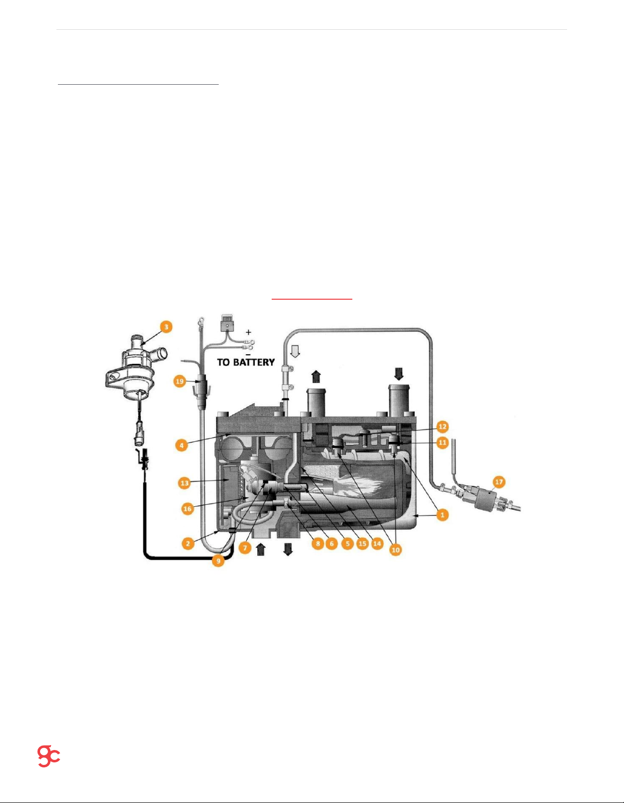
STRUCTURE ............................... 3
EXPLODED PARTS DIAGRAM ................... 4
DIMENSIONS, mm........................... 5
ALLOWABLE MOUNTING ANGLE ................. 5
FUEL PUMP ANGLE & SUCTION HEIGHT ......... 8
FUEL LINE CONNECTIONS .................... 9
FUEL STANDPIPE.......................... 10
WIRING DIAGRAM ......................... 13
CONNECTIONS ............................ 14
TIMER CONNECTIONS ...................... 14
OPERATING INSTRUCTIONS.................. 15
CHANGING LANGUAGE .................... 15
PRE-SETTING HEATING TIMES............. 16
MAINTENANCE .......................... 16
INSPECTION CHECKLIST.................. 16
ADDITIONAL PRECAUTIONS................ 17
TROUBLESHOOTING ........................ 18
TABLE OF CONTENTS

WALRUS 5000C
Page | 3
INTRODUCTION
WALRUS 5000C is a 5kW modulating
diesel fired water heater, which is suitable for
providing hot water for heating purposes via
radiators or matrix heaters and also domestic
hot water via a calorifier. The WALRUS 5000C
is fully automatic in operation featuring low
energy glow pin ignition and microprocessor
control for full temperature regulation. It
has low servicing costs due to modular
construction and its simple wiring means
simple, 2wire system thermostats can be added
into the installation. It can be applied to
various heating purposes, whether its hot water
heating for easier living or engine pre-heating
and demisting. For both vehicle and marine
markets, WALRUS 5000C is a great way to
efficiently meet your heating needs. This
kit includes everything necessary for
installation excluding plumbing to the
radiators and calorifiers.
STRUCTURE
1. Heat Exchanger Assembly
2. Base Cover
3. External Water Pump
4. Fan Cover
5. Glow Pin Lining
6. Glow Pin
7. Glow Pin Housing
8. Flame Sensor
9. Holder
10. Temperature and Overheat Sensor
11. Temp sensor ‘O’ Rings
12. Leaf Spring
13. E.C.U.
14. Combustion Chamber
15. Combustion Chamber Seal
16. Air Motor
17. Fuel Pump
18. Timer Control
19. Main Wiring Harness

WALRUS 5000C
Page | 4
EXPLODED PARTS DIAGRAM
1. Heater Cover
2. Heater Mounting Bracket
3. Combustion Air Intake Clamp
4. 22mm Combustion Air Intake
5. Combustion Air Fixing ‘P’ Clip
6. Exhaust Clamp
7. 24mm Exhaust - 1M (*)
8. Exhaust ‘P’ Clip
9. 24mm Exhaust Silencer*
10. Exhaust Mounting Bracket
11. Exhaust Silencer Clamp*
12. Fuel Standpipe
13. Inline Fuel Filter
14. Fuel Pump
15. Fuel Pump Bracket
16. Anti-Vibration Mount
17. Rubber Fuel Connector
18. Fuel Line Connector Clamp
19. Fuel Damper (Optional)
20. Rubber Coolant Pipe
21. Coolant Pipe Connectors
22. Bypass Valve (**)
23. Reducing Pipe Connectors
24. Coolant Pipe Clamps
25. Coolant Pipe Clamps
26. Fuel Pump Power Loom
27.Fuse Holder
28. Matrix Heater Relay
29. Main Wiring Harness
30. Heater body Loom and Plug
*Combined 2.3m stainless steel exhaust and silencer for marine applications
**Only supplied in vehicle applications

WALRUS 5000C
Page | 5
Do not install the heater anywhere near
flammable sources, including the fuel tank, in
closed spaces without ventilation or exposed in
the proximity of people without a proper heat
shield.
DIMENSIONS, mm
The heater should ideally be installed in
the engine room, but with ease of access for
removal and servicing of the unit.
The main heater body is mounted onto a
suitable surface with a bracket. Ensure it is
lined up with all relevant holes in the correct
position. Once it is in place the unit can be
mounted to the bracket with the M6X10 bolt
supplied in the kit.
ALLOWABLE MOUNTING ANGLE
A. Combustion Air Inlet
B.
Exhaust Outlet
C.
Fuel Inlet
D.
Coolant Outlet
E.
Coolant Inlet

WALRUS 5000C
Page | 6
1.Matrix Heater 2. The Heater 3. External Water Pump 4. Engine
The figure above shows the installation
of the coolant circulation system in a marine
application, not using a bypass valve. Figure
below shows the way to install the system in a
vehicle, using the bypass valve.
1. Matrix Heater 2. The Heater 3. Bypass Valve 4. External Water Pump 5. Engine
To bleed the system, simply loosen the
outlet hose from the heater and begin the system.
Any excess air should immediately circulate out
of the system and the hose can be re-tightened.
During installation, any existing coolant in the
system should be flushed out with clean water and
then re-filled with new coolant. Ensure you use
the right coolant specified for your vehicle.

WALRUS 5000C
Page | 7
1. Heater
2. P-Clip
3. Air Silencer or End Cap
4. 20mm Combustion Air Intake
5. Exhaust P-Clip
6. Exhaust Silencer
7. 24mm Exhaust with End Cap
8. Exhaust Clamps (*)
Figure above shows the installation of the
air intake and exhaust. Make sure you only use
the appropriate pipes provided and use the clamps
to secure them in position.
The air inlet pipe is used to bring in
combustion supporting air into the furnace of the
heater from outside of the vehicle and in the
opposite direction of travel to ensure that the
air is clean and doesn’t clog up the pipe with
dirt and dust.
(*) Not necessary when the silencer is
built into the exhaust as part of a marine
application for example.
Make sure that the exhaust and any other
parts that become hot during the operation of the
heater are away from anything damaged by a high
heat like wires or plastics.
Also, please ensure that the exhaust does
not exit in such a way that the fumes are re-
circulated by the air inlet pipe or can be
inhaled by anyone.
The mounting bracket is supplied in the
installation kit, along with a 100mm M6 hex bolt, used
to secure the heater in place to the bracket using one
of the two M6 taps, located near the center of the
bracket.

WALRUS 5000C
Page | 8
FUEL PUMP ANGLE & SUCTION HEIGHT
1. Heater Body
2. Max. Fuel Level
3. Min. Fuel Level
4. Fuel Pump
A. 3000mm
B. 500mm
C. 2000m
D. Not acceptable
E. Acceptable (between 15-
19°)
F. Not acceptable
Figure shows the ideal way to mount the fuel pump. The fuel pump’s outlet
should tilt upward at an angle between 15˚-35˚ (as shown above).
1. Fuel Tank
2. Fuel Standpipe
3. Fuel line Hose Clamp
4. Fuel Line
5. Rubber Fuel Connector
6. Fuel Filter
7. Fuel Pump
8. To Heater

WALRUS 5000C
Page | 9
FUEL LINE CONNECTIONS
1. Fuel Connector Clamp 2. Fuel Pipe 3. Rubber Fuel Connector
Figures on this page show the correct way
to connect fuel lines to prevent the build-up of
air bubbles: Ensuring they are flush and
minimizing bends.
When the fuel is being sucked from the
vehicle tank, or an independent tank, a fuel
standpipe is required. Make sure all the openings
are appropriate for the installation and a tight
seal is maintained for the base of the standpipe
(see pages 10-11).
The bottom of the suction pipe should be
about 30-40mm from the bottom of the fuel tank,
to avoid sucking impurities or sediment from the
bottom.

WALRUS 5000C
Page | 10
Only use the fuel line provided, ensure
the pipe is placed away from any possible debris
and avoid any sagging in the line. Make sure the
fuel line does not flow downward toward the fuel
pump. This will prevent correct fuel flow and
produce air bubbles in the line.
The fuel filter, fuel pipe and clamps should all be replaced after approximately 2 years of use.
This figure shows the allowable, installations angle of the fuel
filter, as well as the direction of fuel flow (arrow A). The filter
should be fitted between the vehicles tank and the fuel pump.
FUEL Pick-up Tubes
A Fuel pick-up tube will need to be
installed in the vehicle’s fuel tank or an
independent fuel tank depending on what the
installation calls for. Sealant is not required
to fit the pick-up tubes.
Depending on the pick-up tube provided in the
kit, you will need to install the pick-up tube
in one of two ways.
Usually supplied in Marine kits and supplied bent, this standpipe is installed like so:
•Drill a hole in the top of the vehicle’s fuel tank Φ22 ± 0.2mm in size. Ensure it is smooth
and clean of burrs
•Remove the top nut and washers and bend the standpipe straight
•Straighten the standpipe and cut it down to size if necessary
Indice
Altri manuali General Components Stufa
Manuali Stufa popolari di altre marche

Empire Heating Systems
Empire Heating Systems WCC65 Manuale utente

Wetekom
Wetekom 92 86 43 Manuale utente

Desa
Desa SPC170-F Manuale utente

Watlow
Watlow Watrod Electric Tubular Heaters Manuale utente

Haverland
Haverland ECO-DRY GPS Series Manuale elenco delle parti

Stelpro
Stelpro ASILVC2060 Series Manuale utente


