geratech EGE-MSI-848 Manuale utente

EGE-MSI-848
8x8 Modularized Enclosure
(482 mm×380 mm×100 mm)


EGE-MSI-848
8x8 Modularized Enclosure
(482 mm×380 mm×100 mm)
3
DISCLAIMERS
The information in this manual has been carefully checked and is believed to be accurate.
Geratech Technology assumes no responsibility for any infringements of patents or other
rights of third parties which may result from its use.
Geratech Technology assumes no responsibility for any inaccuracies that may be
contained in this document. Geratech also makes no commitment to update or to keep
current the information contained in this document.
Geratech Technology reserves the right to make improvements to this document and/or
product at any time and without notice.
COPYRIGHT NOTICE
No part of this document may be reproduced, transmitted, transcribed, stored in a retrieval
system, or any of its part translated into any language or computer le, in any form or by
any means—electronic, mechanical, magnetic, optical, chemical, manual, or otherwise—
without express written permission and consent from Geratech Technology.
© Copyright 2011 by Geratech Technology.
All Rights Reserved.
Version 1.1 August 2011
TRADEMARK ACKNOWLEDGMENTS
All products or service names mentioned in this document may be trademarks of the
companies with which they are associated.

EGE-MSI-848
8x8 Modularized Enclosure
(482 mm×380 mm×100 mm)
4
SAFETY PRECAUTIONS
Please read all instructions before attempting to unpack, install or operate this equipment
and before connecting the power supply.
Please keep the following in mind as you unpack and install this equipment:
• Always follow basic safety precautions to reduce the risk of re, electrical shock and
injury to persons.
• To prevent re or shock hazard, do not expose the unit to rain, moisture or install this
product near water.
• Never spill liquid of any kind on or into this product.
• Never push an object of any kind into this product through any openings or empty slots
in the unit, as you may damage parts inside the unit.
• Do not attach the power supply cabling to building surfaces.
• Use only the supplied power supply unit (PSU). Do not use the PSU if it is damaged.
• Do not allow anything to rest on the power cabling or allow any weight to be placed
upon it or any person walk on it.
• To protect the unit from overheating, do not block any vents or openings in the unit
housing that provide ventilation and allow for sufcient space for air to circulate around
the unit.
REVISION HISTORY
VERSION NO. DATE (DD/MM/YY) SUMMARY OF CHANGE
RDV1 27/11/14 Preliminary Release
RDV2 19/01/15 EDID naming
RDV3 05/03/15 Add IR Command
RDV4 23/04/15 Add IR Pin Assignment
VS0 27/04/15 Updated Text/Diagrams
RDV5 16/11/15 5Play Output Module Add LAN
VS1 15/08/16 Updated IRMASK command
descriptions

EGE-MSI-848
8x8 Modularized Enclosure
(482 mm×380 mm×100 mm)
5
CONTENTS
1. Introduction........................................................ 1
2. Applications ....................................................... 1
3. Package Contents ............................................. 1
4. System Requirements....................................... 2
5. Features.............................................................. 2
6. Operation Controls and Functions .................. 3
6.1 Front Panel..................................................... 3
6.2 Rear Panel...................................................... 5
6.3 Remote Control .............................................. 6
6.4 IR Cable Pin Assignments.............................. 7
6.5 RS-232 Protocols ........................................... 7
6.6 RS-232 and Telnet Commands ...................... 8
6.7 Telnet Control ............................................... 12
6.8 WebGUI Control ........................................... 14
7. Connection Diagram ....................................... 15
7.1 Example Installation (8×8 HDMI Matrix)....... 15
7.2 Input and Output Modules ............................ 16
8. Specications .................................................. 17
8.1 Technical Specications (Enclosure)............ 17
8.2 Technical Specications (Input Modules) ..... 18
8.3 Technical Specications (Output Modules)... 19
8.4 CAT5e/6/7 Cable Specications................... 22
9. Acronyms ......................................................... 23

EGE-MSI-848
8x8 Modularized Enclosure
(482 mm×380 mm×100 mm)
1
1. INTRODUCTION
The 8 by 8 Modular Matrix is designed to allow the switching and distribution of up to
8 source devices to up to 8 connected displays, either directly via HDMI, DVI or via
CAT5e/6/7 outputs to compatible receivers, providing control options (dependent on
module conguration).
Providing unparalleled levels of exibility, with an advanced modular design these models
can be setup in a wide variety of combinations allowing users the ability to tailor the
Matrix to their requirements by simply adding or removing the input or output modules as
required.
In addition, this matrix also features IP control allowing users to access and control the
matrix remotely and also allow additional options for integration of third-party control
systems.
2. APPLICATIONS
• Public information display
• Educational demo
• Professional presentation
• Advertising display
3. PACKAGE CONTENTS
• 1×8 by 8 Modular Matrix Enclosure (including CPU Control Board)
• 1×Input Module Boards - HDMI, DVI, CAT5e/6/7 or VGA (Optional)
• 1×Output Module Boards - HDMI, DVI or CAT5e/6/7 (Optional)
• 1×IR Extender
• 1×IR Blaster
• 1×Remote Control (with Battery)
• 1×Power Cord
• 1×Operation Manual

EGE-MSI-848
8x8 Modularized Enclosure
(482 mm×380 mm×100 mm)
2
4. SYSTEM REQUIREMENTS
• Up to 8 HDMI, DVI, CAT5e/6/7 or VGA source devices (dependent on module
conguration) connected with appropriate cables.
• Up to 8 displays (TV or monitor) or AV receivers, equipped with HDMI, DVI, CAT5e/6/7
connection (dependent on module conguration) connected with appropriate cables
• Industry standard CAT5e/6/7 cable (for CAT5e/6/7 inputs/outputs)
• Compatible PoC HDBaseT™ Transmitters/Receivers for CAT5e/6/7 Input/Output
modules
5. FEATURES
• HDMI, HDCP 1.1 and DVI 1.0 compliant
• Interchangeable input and output modules
• Input and output module types can be mixed with HDMI, DVI, CAT5e/6/7 and VGA (Input
Only) connection types
• Supports a wide range of PC and HDTV resolutions from VGA to WUXGA and 480i to
1080p and 4K2K@24/25/30
• Supports pass-through of LPCM 7.1CH, Dolby TrueHD, Dolby Digital Plus and DTS-HD
Master Audio
• Supports control of the matrix via on-panel, RS-232, Telnet and WebGUI controls
• Supports 8 available preset settings
• Support 3 EDID modes: Standard, Dynamic and Manual (see Section 6.1 for details)
• Supports HDMI cable input and output lengths of up to 15m each way (1080p@8-bit
resolution), 10m (1080p@12-bit resolution) or 5m (4K2K@30 resolution)
• Supports CAT5e/6/7 cable input and output lengths of up to 100m (1080p@8-bit/12-bit
resolution) or 70m (4K2K@30 resolution) dependent on board capabilities
• HDBaseT 5Play™ convergence supports HD Video, HD Audio, PoC, Ethernet and IR/
RS-232 Control
• HDBaseT 4Play convergence supports HD Video, HD Audio, PoC and IR/RS-232 Control
• HDBaseT 3Play convergence supports HD Video, HD Audio and IR/RS-232 Control

EGE-MSI-848
8x8 Modularized Enclosure
(482 mm×380 mm×100 mm)
3
6. OPERATION CONTROLS AND FUNCTIONS
6.1 Front Panel
19752
3
4
6 8 10 11 12 13
1
LCM: Displays the setting information of each input/output and other setting information
according to the selected mode.
2
IR WINDOW: Accepts the IR remote control signal for the matrix only.
3
POWER: Press this button to turn the matrix on or press it again to put the matrix into
standby mode. The LED will illuminate when the unit is in standby mode.
Note:IftheLEDisashingitmeansthetemperatureinsideistoohighandaircirculation
mayhavebeenrestricted.
4
LOCK: Press this button to lock all the function buttons on panel. The LED will
illuminate, to unlock press it again.
5
MENU: Press this button to enter the menu to change the following settings:
• EDID: Support 3 EDID modes.
1.StandardMode: Uses the built-in EDID settings that support video up to 1080p@60
or WUXGA@60 (RB) video and LPCM 2CH audio.
2.DynamicMode: Reads the EDID settings from the display connected to the lowest
numbered output port.
3.ManualMode:Supports independent EDID settings by selecting the input and output
ports.
• IP: Displays the setting information of IP address, IP Netmask and IP Gateway.
• Temperature: These gures show the internal temperature of the matrix.
• LCM: Supports LCM contrast range from 1 to 4.
6
RETURN: Press this button to return back or exit the current selection.
7
SAVE: Press this button to store the present Input/Output conguration to one of the 8
available preset settings.
8
RECALL: Press this button to recall a previously stored preset setting.
9
ALL: Press this button to assign all outputs to one input.
10
ENTER: Press this button to conrm a setting or selection in the menu.

EGE-MSI-848
8x8 Modularized Enclosure
(482 mm×380 mm×100 mm)
4
11
PAGE ( / ): Use these buttons to cycle through the LCM’s pages for displaying the
current I/O status or when entering into the settings menu.
12
NUMBERS (1~8): Use to select the appropriate numbered input or output.
13
OUT/IN: Press to assign the source to be displayed on the required output. The
sequence should be OUT/IN→Select the Input→OUT/IN→a Select the output→Enter.
EGE-MSI-848
8x8 Modularized Enclosure
(482 mm×380 mm×100 mm)
5
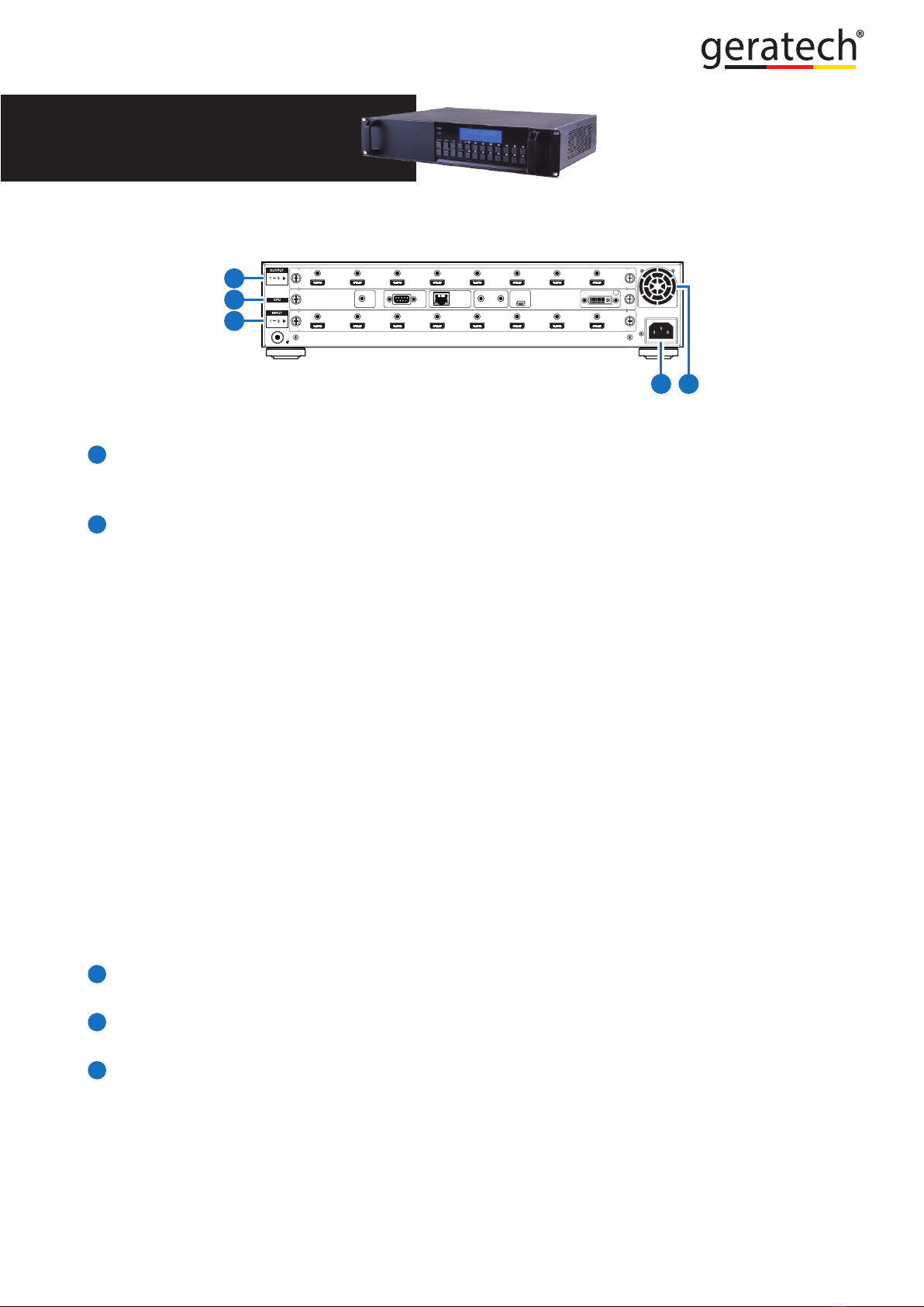
6.2 Rear Panel
100-240VAC
50/60 Hz
OUTPUT
MODULE
INPUT
MODULE
RS232 CONTROL IR ALL
OUTIN
SERVICE OUTPUT 0
IR IN
2
1
3
45
Note:Theabovepanelisanexampleof8×8HDMIconguration.
1
OUTPUTS 1~8: Install an Output module as required for connection to up to 8 displays
(TV or monitor) or CAT5e/6/7 outputs or compatible HDBaseT receivers (dependent on
module conguration).
2
CPU (Control Board)
IR IN: For IR control of the matrix only. Connect to the IR Extender for IR signal
reception of the IR remote control of the matrix. Ensure that the remote being used is
within the direct line-of-sight of the IR Extender.
RS-232: Connect to a PC/Laptop with a D-sub 9-pin cable for RS-232 command
sending and controlling over the Matrix.
CONTROL: Connect to an active network for LAN serving and Telnet/WebGUI control.
LAN serving on compatible HDBaseT input/output modules and transmitters/receivers
only.
ALL IR OUT: Connect the IR output to the IR Blaster for IR signal transmission of the
equipment to be controlled. Place the IR Blaster in direct line-of-sight of the equipment
to be controlled.
ALL IR IN: Connect the IR input to the IR Extender for IR signal reception of the IR
remote control of the equipment to be controlled. Ensure that remote being used is
within the direct line-of-sight of the IR Extender.
Note:ForIRcontroloftheHDBaseTinput/outputmodulesandtransmitters/receivers
only.IRsignalsreceivedbyallIRExtendersconnectedtothetransmitters/receiverswill
betransmittedbyallIRBlastersconnectedtothetransmitters/receivers.
SERVICE: Firmware update only.
3
INPUT 1~8: Install an Input module as required for up to 8 source devices or CAT5e/6/7
inputs for compatible HDBaseT transmitters (dependent on module conguration).
4
POWER SUPPLY: The matrix will automatically turn on when connected to an active
power supply.
5
VENTILATION FAN: This fan will automatically operate when the matrix is switched on.
Do not block the exhaust of the fan or cover it with any object. Please allow adequate
space around the unit for air to circulate freely.
Indice
Altri manuali geratech Allegato


 Manuale utente")


