Giada DF612 Manuale utente

- 1 -

Statement
The copyright of this manual belongs to Shenzhen JIEHE Technology Development Co., Ltd.
(Giada, JIEHE’s global brand) and all rights are reserved. The company reserves the right to
change this manual at any time without notification. Specifications here are for reference only,
please take the real product as standard.
Without official authorization of Giada, other company or individual may not copy, plagiarize,
translate or disseminate this manual for commercial purpose.
The information provided in this manual is accurate and reliable. The company does not take
any legal responsibility for the consequences of infringement use of this manual.
Safety Notice
• Read the user manual carefully before setting up the Giada product.
• Disconnect the power cord before installing the internal components
• Most electronic components are sensitive to static electrical charge, please wear a
wrist-grounding strap when installing the internal components.
• Don’t disconnect the power cord when the system is running to avoid damage to the
sensitive components by instantaneous surge voltage.
Contact Information
Shenzhen JIEHE Technology Development Co., Ltd.
Website: www.giadatech.com
Phone: +86-755-3330 0336
Email: support@giadatech.com
Address: 1~2/F, Block A, Tsinghua Information Harbor, North Section, Shenzhen Hi-tech
Park, Nanshan District, Shenzhen, China

- 1 -
Table of Contents
1. Product Introduction ...................................................................................... 3
2. Interface Description and Hardware Specifications .................................... 3
2.1 Interface Description .................................................................................. 3
2.2 Hardware Specifications ............................................................................. 4
3. Accessories Installation Steps ......................................................................... 5
3.1 Memory Installation ..................................................................................... 5
3.2 SSD(M.2) Installation................................................................................... 6
3.3 WIFI(M.2) Installation ................................................................................. 6
3.4 SIM Card Installation ................................................................................... 7
3.5 3G/4G/5G Installation .................................................................................. 8
4. BIOS Setup ....................................................................................................... 9
Notice ................................................................................................................. 9
A. State of BIOS Setup ...................................................................................... 9
B. Function Keys definitions ............................................................................ 10
C. Auxiliary information Main interface........................................................... 10
4.1 Main (Standard CMOS) Setup .................................................................. 12
4.2 Advanced BIOS Setup ............................................................................... 13
4.2.1 ACPI Settings .................................................................................... 14
4.2.2 CPU Configuration ........................................................................... 14

- 2 -
4.2.3 Wake Configuration .......................................................................... 16
4.2.4 Trusted Computing ........................................................................... 17
4.2.5 IT8625 Super IO Configuration........................................................ 19
4.2.6 System Devices Configuration.......................................................... 21
4.3 Security .................................................................................................... 22
4.4 Boot Menu ............................. .................................................................... 24
4.5 Save & Exit ................................................................................................. 26
4.6 MEBx ...........................................................................................................27
5. JAHC Introduction ......................................................................................... 27
5.1 Auto Power on ............................................................................................ 27
5.2 JAHC Software ........................................................................................... 30
5.2.1 JAHC Software Functions ................................................................. 30
5.2.2 JAHC Software Installation Guide ................................................... 30
5.2.3 Startup and Shutdown Time Setup .................................................... 33
5.3 Watchdog API and Instruction ................................................................... 35

- 3 -
1. Product Introduction
Based on Intel®Alder Lake platform, Giada DF612 is a fanless model featured with Intel®Core
processors. With one DP and two HDMI display outputs, the DP port supports max 8K resolution
and the two HDMI supports max 4K resolution. The player is suitable to be applied in high-end
Digital signage, Kiosk etc. applications.
2. Interface Description and Hardware Specifications
2.1 Interface Description
Front I/O Port
Rear I/O port

- 4 -
2.2 Hardware Specifications
DF612
DF612
Processor
CPU
Intel®CoreTM i3-1215U/i5-1235U/i7-1255U
E-Core Frequency
3.30 GHz/3.30 GHz/3.50 GHz
P-Core Frequency
4.40 GHz/4.40 GHz/4.70 GHz
BIOS
AMI Source Code
Chipset
SOC
Memory
Type
DDR4-32400MHz
Socket
2 x SO-DIMM
Max Capacity
64 GB
Graphics
GPU
Intel®UHD Graphics (CoreTM Core i3)/IRIS®Xe Graphics (CoreTM Core i5/i7)
Graphic Engine
DirectX 12.1, OpenGL 4.6, OpenCL 3.0, 8K 60fps 12b 4:2:0 HEVC/VP9/SCC
DP 1.4
1 x DP (Max.7680 x 4320@60Hz)
HDMI 2.0
2 x HDMI (Max.4096 x 2304@60Hz)
Network
Controller
1 x Realtek RTL8111H Gigabit Ethernet/1 x Intel®i219-LM Gigabit Ethernet
Interface
2 x RJ45
I/O Interface
USB
1 x USB3.2 Gen2 (10 Gbps), 4 x USB3.2 Gen2 (10 Gbps), 2 x USB2.0
Serial Port
1 x RS232, 1 x RS232/422/485
Audio
1 x MIC-IN, 1 x AUDIO-OUT
M.2
1 x M-Key M.2 (2242/2280) for PCIe SSD
1 x E-Key M.2 (2230) for WiFi/BT, support Wi-F i5, Wi-Fi 6, Wi-Fi 6E(CNVi)
1 x B-Key M.2 (3042) for 3G/4G
SIM
1 x SIM Slot
Storage
M.2
1 x M-Key M.2 (2242/2280) for PCIe SSD
Operation
System
OS
Windows 10-1909 (64bit) / Windows 11 (64bit) / Linux Ubuntu (64bit)
Power
Power Type
DC-IN
Input Voltage
19V/3.42A
Mechanical
Construction
Metal
Mounting
VESA Mounting kit
Dimension
(W x D x H)
200mm x 150mm x 40mm (7.87” x 5.90” x 1.57”)
Color
Dark Gray
Environment
Operating
Temperature
0-45℃( 32 ℉~ 113 ℉) at 0.7m/s Air Flow
Relative Humidity
95%@40℃(non-condensing)
Certification
CE, FCC Class B
- 5 -
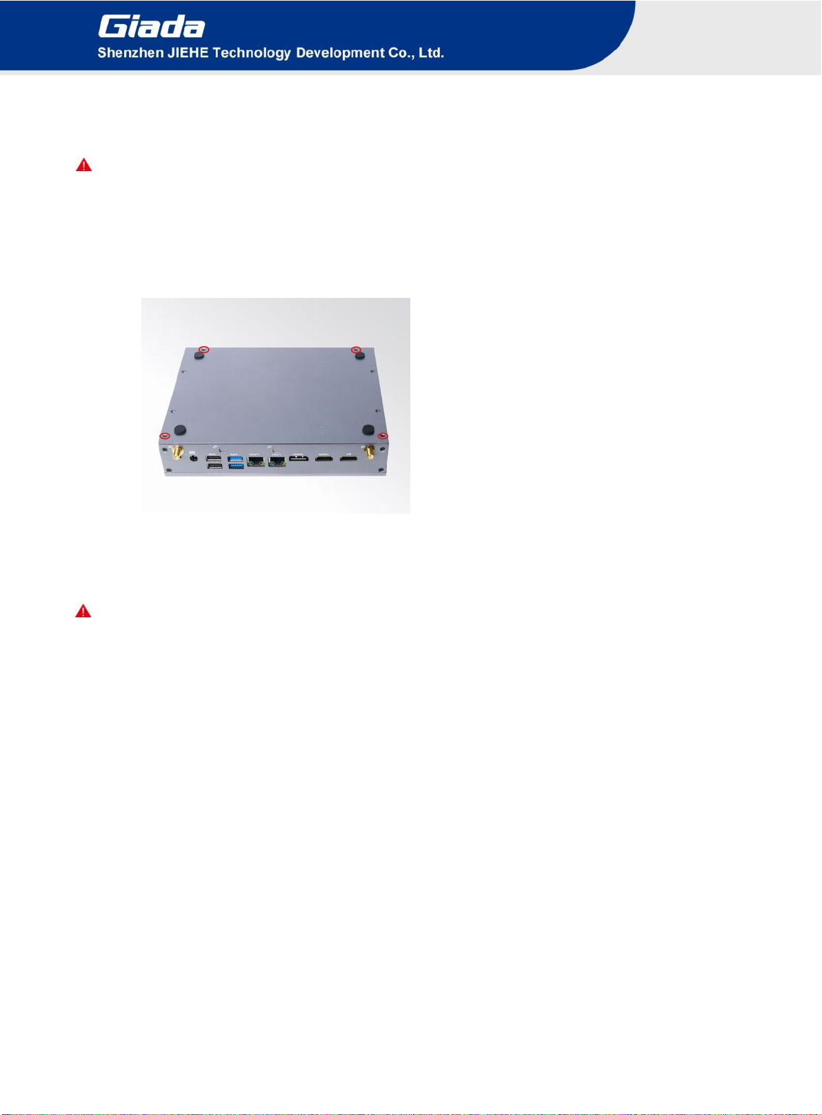
3. Accessories Installation Steps
For safety reasons, please ensure that the power cord is disconnected before opening the case.
How to open the top cover and bottom cover
Unscrew the four screws and then remove the bottom cover. SO-DIMM #1 and #2, M.2 for SSD slot
are at the right side. M.2 slot for 3G/4G, M.2 for Wifi and SIM card slot are at the left side.
3.1 Memory Installation
This product only supports DDR4 SO-DIMM memory modules.
1. Locate the SO-DIMM slot on the board.
2. Gently insert the module into the slot in a 45-degree angle.
3. Carefully push down the memory module until it snaps into the locking mechanism.

- 6 -
3.2 SSD (M.2) Installation
1. Plug the M-Key M.2 (2280) SSD (PCIe protocol) into the appropriate slot.
2. Secure the module to the carrier by tightening up the screw.
3.3 WIFI (M.2) Installation
1. Plug the E-Key (2230) WIFI module into the appropriate slot.
2. Secure the module to the carrier by tightening up the screw.
3. Connect the black cable to Connect the two cables to WIFI module and install the antennas.

- 7 -
3.4 SIM Card Installation
This product supports standard SIM card with the size of 25mm × 15mm.
1. [Open] the SIM card holder and pull it up.
2. Insert the SIM card.
3. [Lock] the card holder.

- 8 -
3.5 3G/4G Installation
3G/4G Installation
Default SMA connector and cable is for WIFI. Please change to 3G/4G SMA connector and cable.
1. Plug the 3G/4G module B-Key M.2 (3042) into the appropriate slot.
2. Secure the module to the carrier by tightening up the screw.
3. Connect the cable to Main and install the antenna.
Indice
Altri manuali Giada Lettore multimediale

Giada
Giada VM23 Manuale utente

Giada
Giada G1568 Manuale utente

Giada
Giada D613 Manuale utente

Giada
Giada F106D Manuale utente

Giada
Giada D612 Manuale utente

Giada
Giada G468 Manuale utente

Giada
Giada DK310 Manuale utente

Giada
Giada VM27 Manuale utente

Giada
Giada PC68 Manuale utente

Giada
Giada D77 Manuale utente


