Gira 2551 20 Manuale utente
Installation and
Operating Instructions
Door Station Stainless Steel Video
2551 20, 2552 20, 2553 20
2554 20, 2556 20, 2558 20
2559 20, 2560 20, 2562 20


3
Table of contents
Device description ......................................................................................................5
Function range of the colour camera...........................................................................6
Coverage range of the colour camera .........................................................................6
Selection of the installation site ..................................................................................7
Installing panel box .....................................................................................................8
Installing front panel .................................................................................................10
Start-up ....................................................................................................................11
Multi-function input ..................................................................................................11
Setting coverage range of the colour camera ............................................................12
Opening Door Station Stainless Steel........................................................................13
Replacing inscription label ........................................................................................14
Operation..................................................................................................................16
Technical data.......................................................................................................... 17
Warranty.................................................................................................................. 18

4

5
Device description
The Door Station Stainless Steel Video is a pre-assembled, vandalism-protected door sta-
tion with colour camera for the Gira door communication system.
The front plate of high-quality V2A stainless steel with a thickness of 3 mm is especially
robust. The call buttons are also made of durable stainless steel. The illuminated inscrip-
tion labels are covered by a fully secured and flameproof glass plate. The inscription labels
can be opened via a covered mechanism and can then removed from the front.
Both the call buttons and inscription labels are uniformly illuminated with a white, power-
saving LED element.
Loudspeaker and microphone are located behind the respective sound openings and are
water-resistant and vandal-proof.
2
36
8
9
10
11
7
4
5
4
4
1
1 Wall anchors (included)
2Panelbox
3Lockingplate
4 Plastic bracket
5Catchstraphook
6 Front panel
7Colourcamera
8Loudspeakercover
9Microphone
10 Name plates
11 Call buttons
6
Function range of the colour camera
The colour camera of the flush-mounted door station has the following product features:
Automatic day/night switching
The camera switches from daytime mode (colour presentation) to night mode (black and
white presentation) and back again at an ambient brightness of 1 Lux. Due to the high
degree of light sensitivity in night mode, good presentation results are achieved even with
poor lighting conditions (to 0.1 Lux). In night mode, the integrated white LEDs ensure an
even illumination of the field of view.
Large coverage range
The colour camera can be swivelled manually by 20º horizontally and vertically during
start-up. A very large field of view in the door entry area results in conjunction with the
100° range of coverage of the camera.
Camera heating
The integrated temperature-dependent camera heating prevents condensation from
forming on the camera cover plate due to fluctuating climactic conditions and thus
provides a clear view.
Camera cover plate
The splash water-resistant camera cover plate made of shock-resistant plastic can be
easily replaced if damaged, for example by vandalism.
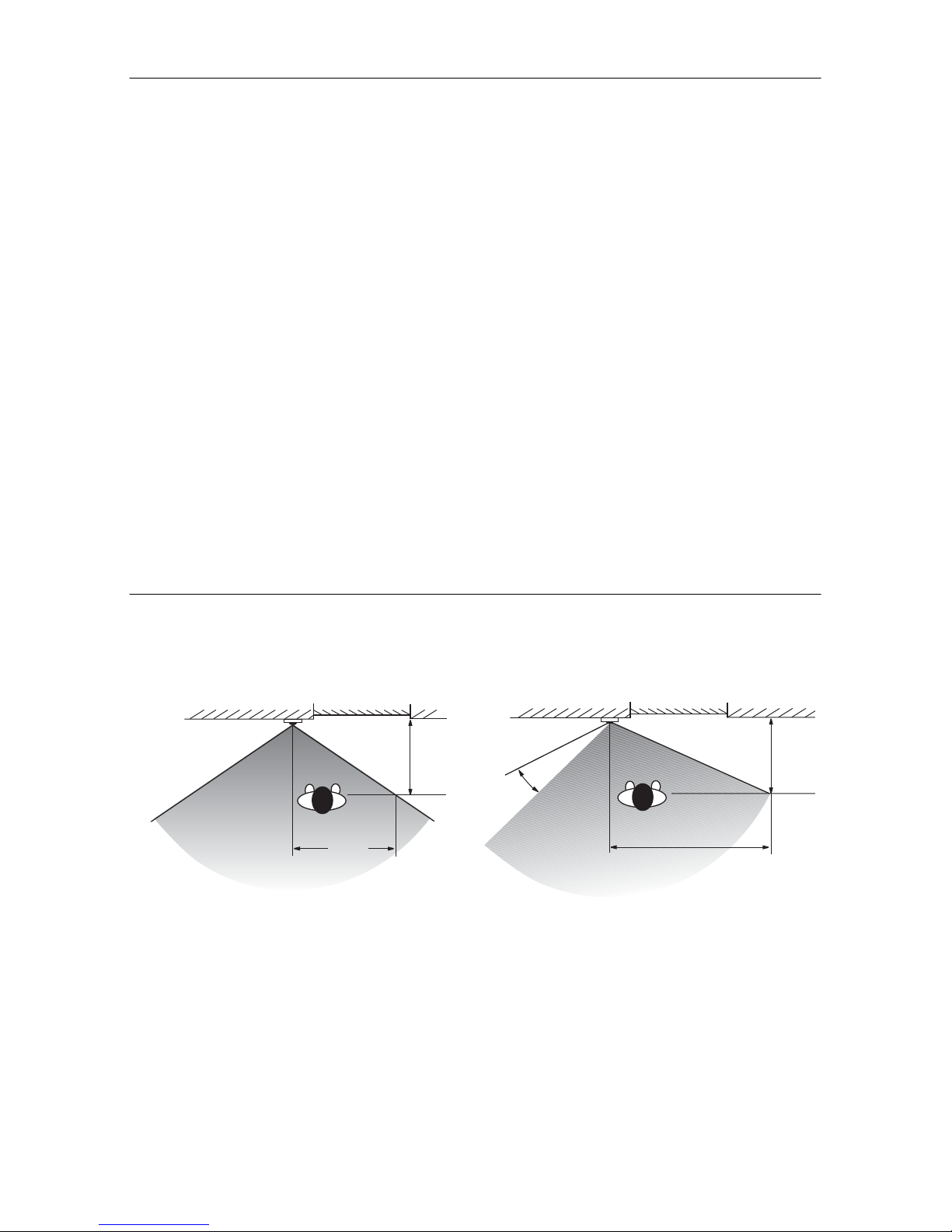
Setting coverage range of the colour camera
The CCD sensor element of the colour camera has an angle of detection of 100°. If this
angle of detection is not sufficient for the required installation scenario, the area can be
manually swivelled by 20° in all directions.
Coverage range of camera with
perpendicular lens.
Coverage range of camera when lens is
swivelled by 20°.
0,6 m
0,7 m
Haustür
Türstation
1,4 m
0,6 m
20°
Haustür
Türstation
7
Selecting the installation site
The selection of the installation site and good illumination are critical for good picture
quality.
No backlighting
Do not point the colour camera towards strong backlighting, such as streetlamps or yard
illumination.
Prevent strong sunlight from hitting the lens.
Picture background
Avoid pointing the camera towards extremely bright image backgrounds and back-
grounds with strong contrasts.
Lighting
LEDs integrated in the camera provide an even illumination of the field of view in dark-
ness.
If the entry area is equipped with additional illumination, this light source must not shine
directly into the camera lens from the front. The best installation site of an external light
source is above the colour camera.
Installation height
The recommended installation height of the colour camera is 1.50 m.
At this installation height, people with an average height of 1.80 m are optimally pre-
sented.
The minimum installation height is 1.20 m.
i
Black and white mode in poor lighting conditions
In poor lighting conditions (< 1 lux) or with the field of view illumination switched on, the
colour camera provides black and white pictures only.
8
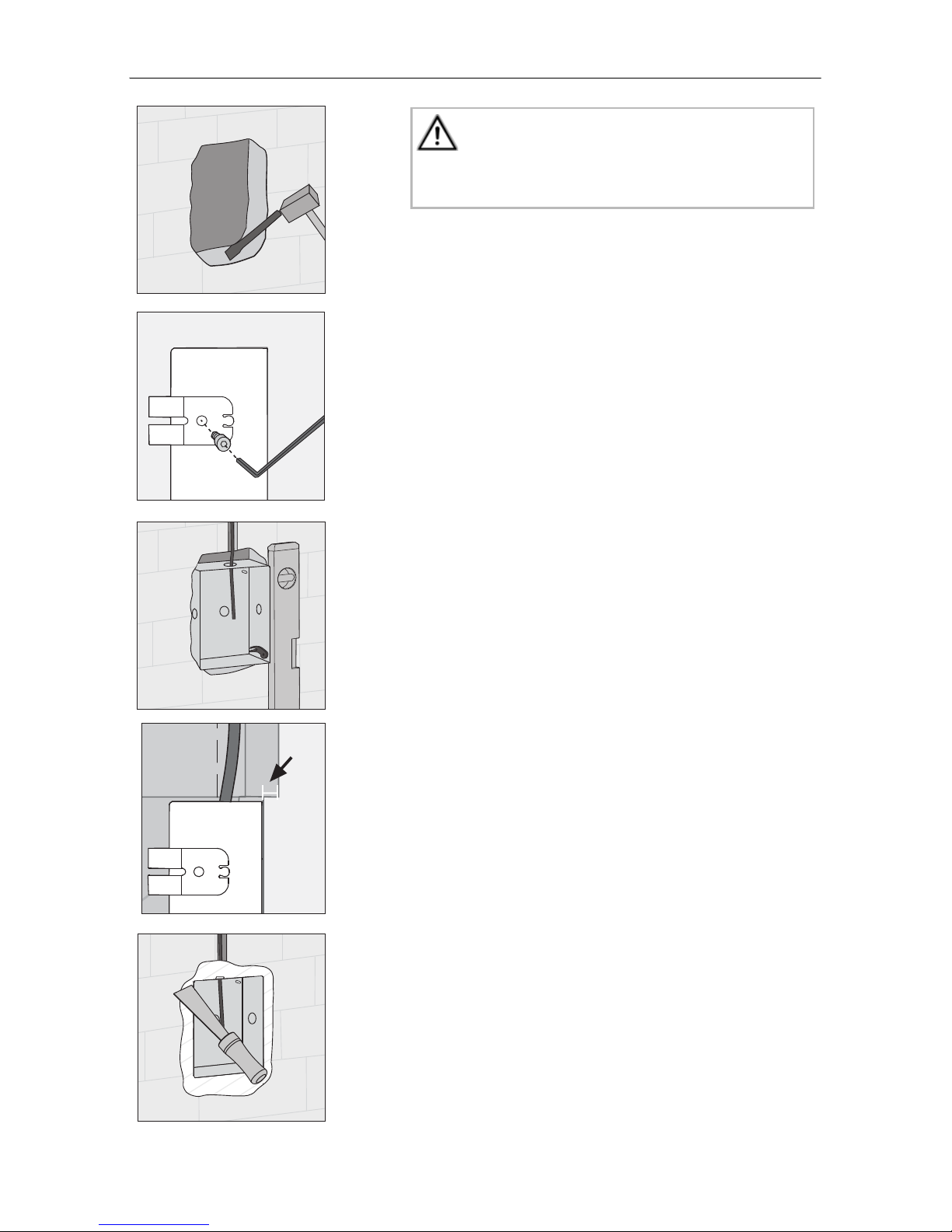
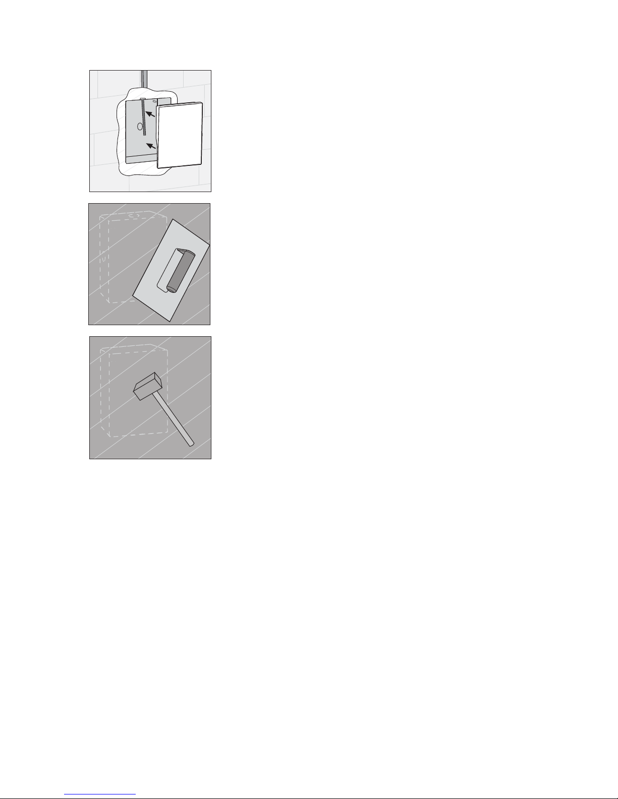
Installing panel box
1. Select a suitable installation site and chisel an open-
ing in the wall.
2. If necessary, mount the included wall anchor.
Note the following information when mounting the
panel box:
• Ensure installation position is correct. (Note the "TOP"
labelling).
• The panel box must be installed level. With the later
mounting of the Door Station Stainless Steel there is
no possibility for correction.
• The panel box must be installed as flush to the surface
as possible!
It must be ensured that the locking plate can be flush-
mounted later. Maximum plaster compensation is
20 mm.
3. Plaster in the panel box to be flush with the final sur-
face (maximum plaster compensation 20 mm).
Attention
Installation and mounting of electrical devices may
only be carried out by a qualified electrician.
max.
20 mm
9
4. Mount the included plaster protection.
5. Plaster the wall.
6. Carefully remove the plaster and take out the plas-
ter protection.
10
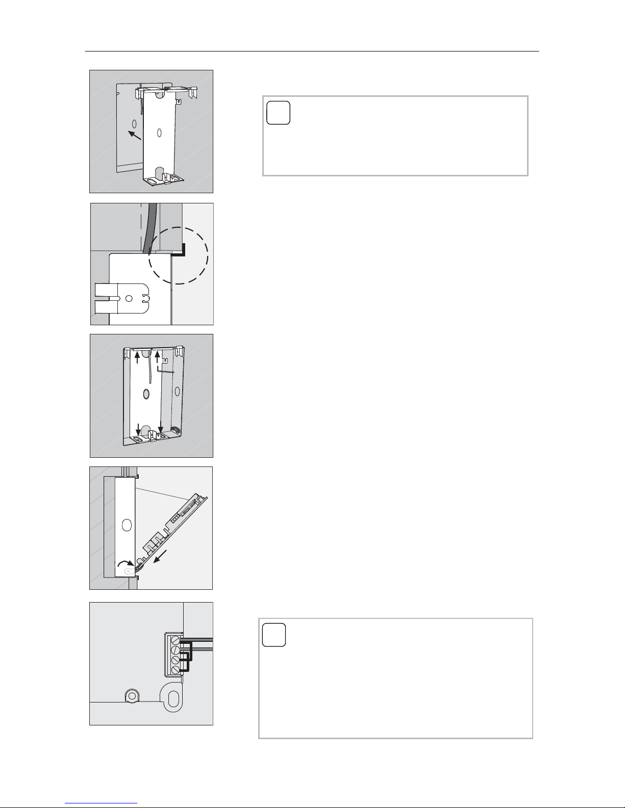
Installing front panel
1. Insert the locking plate flushly into the panel box.
Push the locking plate inwards until the plastic
brackets touch the wall.
2. Fasten the locking plate with the 4 Allen bolts and
locking washers included.
In order to guarantee a secure fastening of the front
panel later, the Allen bolts must be firmly tightened.
3. Fold out both lateral mounting retainers (1.), slide
the front panel of the Door Station Stainless Steel
into the mounting retainers (2.) and attach the catch
strap of the front panel to the hook of the locking
plate (3.).
4. Connect the 2-wire bus to the BUS terminals.
i
Insert locking plate evenly
The locking plate must not be twisted while being
installed into the panel box and must not be under
tension.
2.
1.
3.
ZV BUS
i
Jumpers between BUS and ZV
The wire jumpers between BUS and ZV are required
for operation of the colour camera. Thus the illumina-
tion of the call buttons at the door station cannot be
switched off. If an external power supply is con-
nected to the ZV terminals, the jumpers must be
removed.
Questo manuale è adatto per i seguenti modelli
8
Indice
Altri manuali Gira Sistema di interfono

Gira
Gira 1264 00 Manuale utente

Gira
Gira 1281 Series Manuale di servizio

Gira
Gira 2600 Series Manuale utente

Gira
Gira Surface-mounted video home station 7 Manuale utente

Gira
Gira 1288 00 Manuale utente

Gira
Gira Surface-mounted video home station 7 Istruzioni operative

Gira
Gira 1279 series Manuale utente

Gira
Gira 1269 65 Manuale utente

Gira
Gira 1250 Series Manuale di servizio

Gira
Gira 5919 Series Manuale utente


