
GMI GS700 Manuale utente

User Guide
Gasurveyor 700
Gas Measurement Instruments Ltd

2
Part Number: 49391
Issue: 2
Release Date: 28.03.18
Copyright
© 2016 Gas Measurement Instruments Ltd.
This user guide is copyright of Gas Measurement Instruments Ltd (GMI) and the information
contained within is for use only with Gasurveyor 700 instruments. Reproduction, in whole or part,
without written permission of GMI is prohibited.
Notication Icons
!Warning: Information to help prevent injury or damage
iNote: Notes, tips or additional information

3
Essential Health & Safety Requirements
General
• Read and understand this user guide before operating.
• The instrument must be regularly serviced and calibrated by fully trained personnel in a safe
area.
• Only GMI replacement parts should be used.
• Substitution of components may impair intrinsic safety.
• If the instrument detects gas, follow your own organisation’s procedures and operational
guidelines.
• This equipment is designed and manufactured to protect against other hazards as dened
in paragraph 1.2.7 of Annex II of the ATEX Directive 2014/34/EU.
Battery / Charging
• Alkaline and rechargeable batteries must be exchanged in a safe area and tted correctly
before use.
• Never use damaged batteries or expose to extreme heat.
• Rechargeable batteries must be recharged in a safe area, using the GS700 Charging Cradle.
• Only use approved alkaline batteries.
• Do not mix old and new batteries.
Areas Of Use
• Do not use instrument in potentially hazardous atmospheres containing greater than 21%
Oxygen.
• Exposure to certain chemicals can result in a loss of sensor sensitivity. Where such
environments are known or suspected it is recommended that more frequent response
checks are carried out. Chemical compounds that can cause loss of sensitivity includes
Silicones, Lead, Halogens and Sulphur.
Storage, Handling And Transit
• Batteries should be removed if the instrument is stored for longer than 3 months.
• The instrument can contain electrochemical sensors. Under conditions of prolonged storage
these sensors should be removed. The sensor contains potentially corrosive liquid and
care should be taken when handling or disposing of the sensor, particularly when a leak is
suspected.
• The instrument is designed to handle harsh environments and is IP55 rated. If not subject
to misuse or malicious damage, the instrument will provide many years of reliable service.
Special Conditions Of Use
• Only use permitted external probes specied by certicate number.
• The equipment must not be subject to prolonged exposure to light when not in use.
Any right of claim relating to product liability or consequential damage to any third party against
GMI is removed if the warnings are not observed.
!

4
Equipment Parameters
GS700 Instrument:
Um: 6.78V (Rechargeable Battery, part number - 49221)
Temperature Range: -20oC ≤ Ta ≤ 50oC
GS700 Charger:
Um: 250V
Uo: 6.78V
Temperature Range: -20oC ≤ Ta ≤ 44oC
Certication
Gasurveyor 700 instruments are certied as:
ATEX
II 2 G Ex db ia IIC T4 Gb -20oC ≤ Ta ≤ 50oC
*
II 2 G Ex db ia IIB T3 Gb -20oC ≤ Ta ≤ 50oC
SIRA 15 ATEX2299X
IECEx
Ex db ia IIC T4 Gb -20oC ≤ Ta ≤ 50oC
*
Ex db ia IIB T3 Gb -20oC ≤ Ta ≤ 50oC
IECEx SIR 15.0105X
CSA
Class I, Div.1 Groups A, B, C and D T4
Class I, Zone 1 AEx db ia IIC T4 Gb Ex db ia IIC T4 Gb
*
Class I, Div.1 Groups C and D T3
*
Class I, Zone 1 AEx db ia IIB T3 Gb Ex db ia IIB T3 Gb
* The GS7xx series is certied for use with for Gas Group IIC, Temperature Classication T4
except when the PPM gas sensor is tted. With a PPM gas sensor tted either internally or
externally the GS7xx is certied for Gas Group IIB and Temperature Classication T3.

5
Additional Safety Details - CSA Only
CAUTION: Before each days Usage, test on a known concentration of methane, equivalent to
25 - 50% of full scale concentration. Accuracy must be within 0 to +20% of actual. Accuracy
may be corrected by calibration. (Refer to Chapter: ‘CALIBRATION’).
ATTENTION: Avant chaque utilisation journalière, testez la réaction de l’appareil en utilisant
une concentration connue en méthane, correspondant à 25-50% de la lecture à fond d’échelle.
La précision doit se situer entre 0 et +20% de la valeur réelle. La précision peut se corriger en
étalonnant l’appareil (voir Chapitre: CALIBRATION).
CAUTION: Any rapid up-scale readings followed by a declining or erratic reading may indicate a
gas concentration beyond the upper scale limit, which may be hazardous.
ATTENTION: Toute lecture dépassant rapidement le maximum de l’échelle et suivie par une
diminution ou une lecture erronée, indique une concentration de gaz supérieure à la valeur
maximale de cette échelle. Cette lecture n’est pas signicative.
CAUTION: Substitution of components may impair intrinsic safety.
ATTENTION: le remplacement d’un composant peut porter atteinte à la sécurité intrinsèque du
produit.
CAUTION: Do not charge in a hazardous area. Um = 6.78V.
ATTENTION: Ne pas charger en zone dangereuse. Um = 6.78V.
NOTE: CSA have only assessed the LEL combustible gas detection portion of this instrument
for performance.
NOTE: CSA a seulement évalué la partie LIE pour la mesure des performances en détection de
gaz inammables.
CAUTION: Electromagnetic interference (EMI) signals may cause the instrument operation to
become erroneous.
NOTE: The instrument contains internal checking of sensor sensitivity, which during calibration
will prevent the sensor being calibrated if it has been contaminated or reached its end of life. In
addition to this the Instrument Management System (IMS) can be used to track the condition of
sensors from stored calibration results.

6
Contents
Notification Icons.................................................................................. 2
Copyright............................................................................................... 2
Essential Health & Safety Requirements ........................................... 3
General ..............................................................................................................................3
Battery / Charging .............................................................................................................3
Areas Of Use.....................................................................................................................3
Storage, Handling And Transit............................................................................................3
Special Conditions Of Use.................................................................................................3
Equipment Parameters......................................................................................................4
Certification ........................................................................................... 4
Additional Safety Details - CSA Only .................................................................................5
Getting Started...................................................................................... 9
Overview ...........................................................................................................................9
Key Features......................................................................................................................9
Display ............................................................................................................................. 10
Soft-Keys.......................................................................................................................... 10
Status Bar ........................................................................................................................ 11
Gas Ranges .....................................................................................................................11
Battery Packs...................................................................................................................12
Operation............................................................................................. 13
Switch On ........................................................................................................................13
Warm-up Sequence.........................................................................................................13
Switch Off........................................................................................................................14
Soundness Test (Optional) ...............................................................................................15

7
Modes of Operation............................................................................ 16
Gas Leak Outdoors (GLO) ............................................................................................... 17
Barhole Testing ................................................................................................................18
Conned Space Monitoring (CSM) ..................................................................................20
Purge ...............................................................................................................................22
Search..............................................................................................................................22
Pipeline Gas Test .............................................................................................................23
Alarms ................................................................................................. 24
Alarm Acknowledge.........................................................................................................24
Gas Alarm Types ..............................................................................................................25
Alarm Mute......................................................................................................................27
Condence Signal ...........................................................................................................27
Fault Alarm Types.............................................................................................................28
Battery / Charging............................................................................... 30
Replacing Alkaline Batteries.............................................................................................30
Recharging the Battery Pack............................................................................................32
Replacing the Battery Pack ..............................................................................................35
Maintenance........................................................................................ 36
Cleaning...........................................................................................................................36
Probe Handle Filter Replacement....................................................................................36
Replacing the Dust Filter .................................................................................................37
Calibration........................................................................................... 38
Automatic Calibration ......................................................................................................38
Manual Calibration ...........................................................................................................38
Calibration Validity............................................................................................................38
Accessories / Spares........................................................................... 39
Accessories .....................................................................................................................39
Common Spares..............................................................................................................40

8
Specification........................................................................................ 41
Instrument Performance..................................................................................................41
Instrument Specication..................................................................................................42
Alarm Set-points..............................................................................................................43
Soft-Key Button Glossary.................................................................................................44
Appendix A.......................................................................................... 45
Field Calibration (Optional)...............................................................................................45
Warranty ............................................................................................. 47
Liability ................................................................................................ 47
Customer Support .............................................................................. 47
Disposal .............................................................................................. 47
Contact Details.................................................................................... 48

9
Getting Started
Overview
The Gasurveyor 700 (GS700) is the rst choice
for all gas utility applications.
Reliable measurements are performed using
innovative infrared sensing technology including
instantaneous conrmation that the gas sample
is natural gas.
This lightweight, rugged instrument is easy to
use thanks to an intuitive menu layout on a large
display.
Key Features
Gas Exhaust
Semiconductor
Probe Connection
(Optional)
Harness Clip
Base Screw
(Battery Pack)
Base Screw
(Battery Pack)
Visual Alarm
(360oLED bar)
Buzzer
Gas Inlet Nozzle
(with dust lter)
Charging Contacts
(Rechargeable only)
Harness Clip
Visual Alarm
(360oLED bar)
Right
Left
GS700 USER GUIDE
10
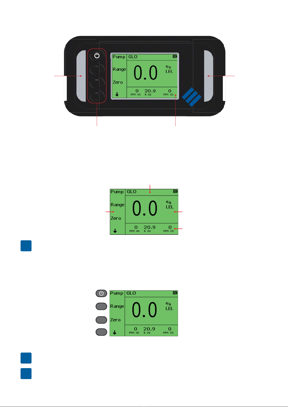
To p
Soft-Keys
(includes power key)
Display
Visual Alarm
Visual Alarm
Display
The GS700 is a fully congurable instrument, the menu structure and information displayed may
vary.
Soft Key Options
Status Bar
Gas Readings /
Information Window 1
Gas Readings /
Information Window 2
iThe above display will be used throughout this user guide as the example main display.
Soft-Keys
The GS700 has 4 soft-keys performing different operations depending on mode and function.
The soft-keys shall be referred to as B1, B2, B3, and B4 throughout this user guide.
iB1 also acts as power on / off.
iFor soft-key menu options, see “Soft-Key Button Glossary”.
B1
B2
B3
B4
Questo manuale è adatto per i seguenti modelli
1
Indice
Altri manuali GMI Rilevatore di gas

GMI
GMI PS1100 Istruzioni operative

GMI
GMI Gasurveyor 700 Manuale utente

GMI
GMI Gasurveyor 500 Series Manuale di istruzioni

GMI
GMI Gasurveyor 3-500 Manuale di istruzioni

GMI
GMI OXYGAS 500 TRAINING Manuale utente

GMI
GMI Oxygas P-500 Manuale di istruzioni

GMI
GMI PPM Gasurveyor 500 Manuale di istruzioni

GMI
GMI Gasurveyor 11-500 Manuale di istruzioni

GMI
GMI PS500 Manuale di istruzioni

GMI
GMI PS500 Manuale di istruzioni


